Iranian Classification Society Rules

< Previous | Contents | Next >
(a) Sampling of test specimens, magnification of photomicrograph and evaluation of dis- continuous surface to be in accordance with requirements in 3205. 3..
(4) Acceptance criteria
The test results based on provisions of (2) and (3) above shall satisfy the following criteria:
(a) ECL(mm) ≤ 2 (for base metal)
(b) no discontinuous surface (e.g., step) between the base metal and weld metal (for welded
joint)
(5) Test report
The test report shall include the following information:
(a) name of the manufacturer
(b) date of tests
(c) chemical composition and corrosion resistant process of steel
(d) test results according to (2) and (3) above
(e) judgement according to (4) above
2. Test on simulated inner bottom conditions
(1) Test condition
Tests on simulated inner bottom conditions in cargo oil tanks (COT) should satisfy each of the following conditions:
216 Guidance for Approval of Manufacturing Process and Type Approval, Etc. 2015
![]()
(a) The test shall be carried out for 72 h for base metal, and 168 h for welded joint.
(b) There are to be at least five test pieces of corrosion resistant steel for base metal and weld- ed joint, respectively. For comparison, at least five test pieces of base metal of conventional
steel should be tested in the same condition.
(c) The conventional steel used should also meet the requirements of Table 3.32.2 of this Appendix. The mechanical properties of the test specimen should be representative of steel used in its intended shipboard application.
(d) Base material is to be prepared such that one surface is to be taken from a position within
2 mm of one rolled surface. The size of each test piece is 25±1mm x 60±1mm x 5±0.5mm. All surfaces are to be ground to bare steel and polished with an emery paper
#600, except a hole for hanging.
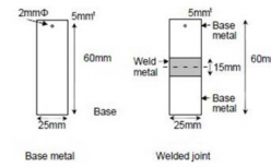
Fig 3.32.5 Test piece
(e) For welded samples, a test assembly is to be made from the same steel cast as the base material test in (d) but may be from a plate of different thickness. The assembly is to be welded using the process and consumable to be approved for use with the base material. The size of the test piece for a welded joint is 25±1mm x 60±1mm x 5±0.5mm, including 15±5mm width of the weld metal part(excluding heat affected zone). This surface is to be ground to bare steel and polished to 600 grit finish.
(f) The samples are hung in a solution from a fishing line (0.3 mm to 0.4 mm in diameter, made of nylon) to avoid crevicelike and/or localized corrosion. An example of a corrosion
test configuration is shown in Fig 3.32.6
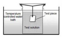
Fig 3.32.6 Simulated corrosion test apparatus for inner bottom
(g) The test solution contains 10 mass% NaCl and its pH is 0.85 adjusted by HCl solution.
The test solution should be changed to a new one every 24 h to minimize pH change of the test solution. The volume of the solution is more than 20 cc/cm2 (surface area of test piece). The temperature of the test solution is to be kept at 30 ± 2°C.
(2) Test results of base metal
(A) Prior to the testing, the following data shall be measured and reported:
(a) size and weight of test piece.
(B) After the testing, the following measured data shall be reported:
(a) weight loss (difference between initial weight and weight after testing)
(C) Specimens are to be weighed to an accuracy of ± 1 mg.
(D) Corrosion rate (C.R.) calculated by the following formula:
Guidance for Approval of Manufacturing Process and Type Approval, Etc. 2015 217
![]()
×
×
×
W: Weight loss(g), S: Surface area(cm2), D: Density(g/cm3)
(E) To identify specimen which hold crevice and/or localized corrosion, the C.R. is to be plot- ted on a normal distribution statistic chart. One specimen that has a corrosion rate deviating from the average corrosion rate by more than +25% may be eliminated from the results, provided that the cause of the accelerated corrosion is demonstrated to be due to localized corrosion around the hanging hole and/or stamp (e.g. crevice corrosion, pitting corrosion, etc.). C.R. data which deviate from the normal statistical distribution must be eliminated from the test results. An example is shown in Fig 3.32.7 for reference.
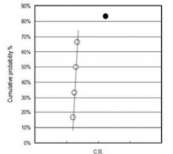
Fig 3.32.7 An example of plot of C.R.s on a normal distribution chart
(In this case C.R. data • should be abandoned and eliminated.)
(F) Calculation of average of C.R.'s data (C.R. ave)
(3) Test results of welded joint
(A) Sampling of test specimens, magnification of photomicrograph and evaluation of dis- continuous surface to be in accordance with requirements in 3205. 3..
(4) Acceptance criterion
The test results based on (2) and (3) above shall satisfy the following criteria:
(A) C.R.ave (mm/ year) ≤ 1.0 (for base metal)
(B) no discontinuous surface (e.g., step) between the base metal and weld metal (for welded
joint)
(5) Test report
The test report shall include the following information:
(A) name of the manufacturer
(B) date of tests
(C) chemical composition and corrosion resistant process of steel
(D) test results according to (2) and (3) above
(E) judgement according to (4) above
3. Interpretation of weld discontinuity
(1) Preparation of samples after corrosion test
(a) All five samples are to be prepared as follows.
(b) Two full thickness specimens approximately 20 mm long x 5 mm wide are to be sectioned with their principle axis perpendicular to the weld fusion line. Each specimen is to be lo-
cated such that the weld fusion line is located approximately at its mid length. See Fig
3.32.8.
218 Guidance for Approval of Manufacturing Process and Type Approval, Etc. 2015
![]()
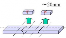
Fig 3.32.8 Sectioning plan
(c) The specimens are to be mounted in resin to allow polishing of the cross section. The specimens are to be etched in Nital after polishing to reveal the fusion boundary.
(d) A photomicrograph is to be taken at a magnification of approximately 100 X.
(2) Evaluation of depth step
(A) On the photomicrograph, construct a line A-B, perpendicular to the corrosion surface through the point where fusion line and the surface cross. See Fig 3.32.9.
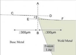
Fig 3.32.9 Determination of corrosion depth on photomicrograph
(B) Construct two parallel lines C-D and E-F one representing the higher level, the other the lower level. Each line is to be constructed over a distance of ≥ 300 μm from line A-B on
the base metal and weld metal side, respectively.
(C) Measure the distance r mm between the intersection point at line A-B and each average surface line on the photomicrograph.
(D) If the intersection point at line A-B and average surface line of welded metal part is above that of base metal part, then the existence of step should be neglected for this sample.
(E) Calculate the depth of discontinuous step R in μm from the actual photomicrograph magni-
fication M as follows.
×
(3) Evaluation of step angle
(A) Evaluation for angle of step is unnecessary if the depth of step calculated on both samples see (2) above, are not greater than 30 μm or if either step exceeds 50 μm for a single
specimen. Otherwise the angle of step is to be calculated as follows.
(B) Produce a photomicrograph at a magnification of approximately 250 X, see Figure 3.32.10.
(C) Draw an average surface line C-D for base metal part and E-F for weld metal part.
(D) Find the closest intersection point with the step of the base metal surface profile and the constructed line C-D and the closest intersection point with the step for weld metal con- structed line E-F respectively, and connect those two intersection points.
Guidance for Approval of Manufacturing Process and Type Approval, Etc. 2015 219
![]()
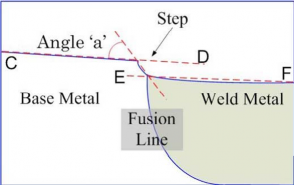
Fig 3.32.10 Calculation of step angle
(E) Measure the angle ‘a’ in degrees given by the line C-D and the connected line described in
(D) above.
(4) Acceptance Criteria
(A) If the depth of both steps are less than or equal to 30 μm then the measurement of angle
is unnecessary, and the sample is considered to be acceptable.
(B) If the depth of steps on both photomicrographs are less than or equal to 50 μm and in ad-
dition if both the measured angles are less than or equal to 15 degrees, then the sample is
considered to be acceptable.
(C) If either of the conditions described in (A) or (B) above are not in compliance, the sample is considered to contain a “discontinuous surface”and fails the test.
(D) Welds should be evaluated as “without discontinuous surface” when all 5 corrosion test samples are considered acceptable.
3206. Type Approval Certificates
1. After completion of the approval test, the manufacturer is to produce the report of test and submit it to the Society.
the approval
2. The Society is to issue a Type Approval Certificate, such as FORM AC-2 shown in Annex 2 of this Guidance to the applicant, where deemed appropriate by the Society on the basis of the sub- mitted test reports after completion of the type test.
3. The Type Approval Certificate for approved corrosion resistant steel is to include the following items:
(1) Brand name, manufacturer and certificate number
(2) Steel grade and area of application designation
(3) Chemical composition range (including additive and/or controlling element percentages to im- prove corrosion resistance)
(4) Maximum thickness
(5) Steelmaking process
(6) Casting process
(7) Delivery condition
(8) Brand of welding consumables and welding method
(9) Period of validity of approval
4. Validity and renewal of approval certificate are to be in accordance with Ch 3, Ch 1, 108. of this Guidance.
3207. Changes in the approved contents
1. Where the scope of approval changes, for example for additions to the applicable welding con- sumables, the effects of these changes are to be subjected to corrosion resistance tests for the weld- ed joints.
220 Guidance for Approval of Manufacturing Process and Type Approval, Etc. 2015
![]()