Iranian Classification Society Rules

< Previous | Contents | Next >
Section 1 Standard for Ship's Facilities
101. Assessment of total resistances
Total resistance(Ĉ )(kg) of floating structures is to be determined by using each mooring method, such that most severe condition can be considered when mooring force is calculated in accordance with the
following ĈᾍÃ, ĈᾍD , Ĉᾼ ,
ĈᾯÃ
and ĈᾯD .
ĈᾍÃ
and
ĈᾍD
: the value obtained from the following
For longitudinal wind : Ĉ
Ņ Å × A
× Đ Ī
(kg)
For transverse wind :
ᾍÃ ᾍÃ Ī ᾍ ᾍ
ÅᾍÃ
ÅᾍD Aᾍ
Đᾍ
ĈᾍD Ņ ÅᾍD × Aᾍ × Đᾍ (kg)
: 0.0429 (longitudinal wind pressure factor) (kg∙secĪÕmĨ)
: 0.0735 (lateral wind pressure factor) (kg∙secĪÕmĨ)
: projected area on the wind directional section above the load line (m Ī)
: relative wind speed (mÕs) (normal: min. 15 mÕs, typhoon: min. 44 mÕs. However, maximum wind speed of the data from Meteorological
Administration may be used.)
Ĉᾼ : the value obtained from the following
Ĉ Ņ LǾÌĪÌĪ A ÓNĐ Ñ Đ
Ń Ī Ñ LǾĮĮLNĐ Ñ Đ
ŃŎ (kg)
ᾼ ᾼ ᾼ ᾯ ᾼ ᾯ
A
: surface area below the waterline (m Ī) ᾼ
ĈᾯÃ
Đᾼ Đᾯ
and
ĈᾯD
: current speed (mÕs)
: moving speed of the structures (mÕs)
: the value obtained from the following
For longitudinal fluid flow : Ĉ
Ņ LǾJ∙ſl ∙ Ǽ
∙ A ∙ NĐ Ñ Đ Ń Ī
(kg)
ᾯÃ ᾎᾘ ᾯ ᾼ ᾯ
Ī
For lateral fluid flow : ĈᾯD Ņ KĮǾĪ Aᾯ ∙ NĐᾼ Ñ Đᾯ Ń
ſl : water density (sea water : 104.5 kg∙ secĪÕmĨ, fresh water :
(kg)
102.0 kg∙secĪÕmĨ)
Ī
Aᾯ : projected area on direction of fluid flow below the load line of the structure (m )
Đᾼ Đᾯ Ǽᾎᾘ
: current speed (mÕs)
: moving speed of the structures (mÕs)
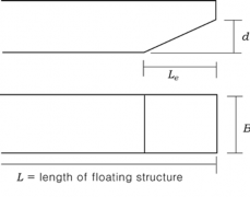
: the value according to the geometry of bow, as given in Table 4.1.1
![]()
Table 4.1.1 Resistance factor, Ǽᾎᾘ
ÃᾙÕᾘ Đᾼ ÕΡ̓ÜÃᾛ | 0 | 1 | 2 | 3 | 4 | 5 | 6 | 7 |
0.08 | 0.710 | 0.245 | 0.150 | 0.117 | 0.106 | 0.100 | 0.098 | 0.096 |
0.10 | 0.755 | 0.260 | 0.160 | 0.128 | 0.111 | 0.107 | 0.103 | 0.102 |
0.12 | 0.805 | 0.280 | 0.180 | 0.138 | 0.121 | 0.113 | 0.108 | 0.105 |
0.14 | 0.850 | 0.305 | 0.200 | 0.152 | 0.131 | 0.122 | 0.115 | 0.111 |
0.16 | 0.905 | 0.325 | 0.225 | 0.165 | 0.144 | 0.131 | 0.122 | 0.117 |
0.18 | 0.960 | 0.380 | 0.249 | 0.181 | 0.156 | 0.142 | 0.130 | 0.120 |
0.20 | 1.025 | 0.455 | 0.285 | 0.201 | 0.170 | 0.154 | 0.140 | 0.132 |
0.22 | 1.120 | 0.550 | 0.335 | 0.222 | 0.187 | 0.168 | 0.153 | 0.141 |
0.24 | 1.230 | 0.670 | 0.400 | 0.258 | 0.208 | 0.187 | 0.170 | 0.156 |
(NOTES) ᾛ : gravity acceleration (9.8 mÕsecĪ) | ||||||||
Ch 4
![]()
102. Standard and provisions for anchor, etc.
1. The floating structures are to be provided not less than total resistance according to
with anchors, anchor chains, etc. of which strength are
101. In this case, safety factor, tensile force acting on
the anchor chain and mass of anchor are as follows:
(1) Safety factor is to be not less than 4.
(2) Tensile force(Dᾏ) acting on the anchor chain is to be obtained from the following formula.
However, inclined angle of anchor chain on direction of total resistance should be considered
when necessary to be considered.
Dᾏ Ņ Ĉ Õ cosß (ß : inclined angle of anchor chain on direction of total resistance in horizontal plane)
(3) Mass of anchor is to be obtained from the following formula:
EŅEᾍ÷LǾKĴĶ
Eᾍ : mass of anchor in the underwater, as obtained from following formula:
Eᾍ Ņ Č Ň Åᾏ × Ãᾏ × Eᾏ Õ Åᾍ
Č : the value multiplying the tensile force(Dᾏ) of the anchor chain by the safety factor.
When there are provided more than one anchor, the value divided by number of an- chors
Ãᾏ : length of anchor chain
Eᾏ : mass of 1 meter of anchor chain under water, to be taken the value multiplying the mass of anchor chain in the air by 0.869.
Type | clay | silt | sandy soil | sand | coarse sand |
Åᾍ | 2 | 2 | 2 | 3~4 | 3~4 |
Åᾏ | 0.6 | 0.6 | - | 0.75 | 0.75 |
Åᾍ and Åᾏ : holding power factor of anchor and anchor chain, as given in Table 4.1.2 Table 4.1.2 Holding power factor
(4) Tensile force(Dᾮ ) acting on the mooring rope is to be taken from following formula:
Dᾮ Ņ Ĉ Õ cos ß (ß : inclined angle of the mooring rope on direction of total resistance in horizon- tal plane)
(5) The specification, etc. of the wire rope and fibre rope are to be given in Table 4.1.3 to
Table 4.1.6.
Ch 4
![]()
2. The floating structures are to be provided with more than two anchors and anchors and anchor chains are to be capable of sustaining total resistance specified in 101.
3. Where stock anchors are used, the mass of anchor excluding the stock may be 0.8 times the mass of stockless anchor.
4. Where anchor having the holding power of 2 times of stockless anchor is used, the mass of an- chor may be 0.75 times the mass of stockless anchor.
5. The anchor providing in forward direction are linked with anchor chains and the length of holding area of chains is to be more than 3 shackles. The length of each chain linked anchor is to be more than the sum length of catenary part and holding part.
6. The anchors to hold a lateral position of structures are to be linked by chains.
103. Anchoring Arrangements
For the floating structures having an anchor of more than 150 kg, appropriate anchoring arrangements are to be provided. However, for the floating structures which are not maneuvering except repairing or deteriorating weather conditions, etc, it may not be provided.
104. Mooring Arrangements
The requirements and types of mooring arrangements of floating structures are to comply with Pt 4, Ch 10 of the Rules.
105. Towing Arrangements
The towing arrangements of floating structures are to comply with Pt 3 in "Rules for the Towing Survey of Barges and Tugboats". However, for the floating structures which are not maneuvering except repairing or deteriorating weather conditions, etc, it may not be applied.
Ch 4
![]()
![]()

Table 4.1.3 Grades of steel wire rope
Grade | No. 1 | No. 2 | No. 3 | No. 4 | No. 5 | No. 6 | No. 21 | |
Sectional view | ||||||||
Composition | Number of wire | 7 | 12 | 19 | 24 | 30 | 37 | 36 |
Number of strands | 6 | 6 | 6 | 6 | 6 | 6 | 6 | |
Fibre core | Centre | Centre and Centre of strand | Centre | Centre and Centre of strand | Centre and Centre of strand | Centre | Centre | |
Composition mark | (6×7) | (6×12) | (6×19) | (6×24) | (6×30) | (6×37) | (6×WS(36)) | |
![]()
Table 4.1.4 Masses and breaking test loads for steel wire ropes
![]()
Ch 4
Grade | No. 1 | No. 2 | No. 3 | No. 4 | No. 5 | No. 6 | No. 21 | |||||||
Composit ion mark | (6×7) | (6×12) | (6×19) | (6×24) | (6×30) | (6×37) | (6×WS(36)) | |||||||
Diameter of steel wire rope (mm ) | Break ing test load (kN ) | Mass per metre in length (kg) | Break ing test load (kN ) | Mass per metre in length (kg) | Break ing test load (kN ) | Mass per metre in length (kg) | Break ing test load (kN ) | Mass per metre in length (kg) | Break ing test load (kN ) | Mass per metre in length (kg) | Break ing test load (kN ) | Mass per metre in length (kg) | Break ing test load (kN ) | Mass per metre in length (kg) |
10 | 52.4 | 0.371 | 33.3 | 0.273 | 47.9 | 0.364 | 45.5 | 0.332 | 41.1 | 0.310 | 48.9 | 0.359 | 50.5 | 0.396 |
12 | 75.4 | 0.534 | 48.0 | 0.393 | 71.6 | 0.524 | 65.5 | 0.478 | 59.1 | 0.446 | 70.5 | 0.517 | 72.8 | 0.570 |
14 | 103 | 0.727 | 65.3 | 0.535 | 97.4 | 0.713 | 89.1 | 0.651 | 80.5 | 0.607 | 96.2 | 0.704 | 99.0 | 0.776 |
16 | 134 | 0.950 | 85.2 | 0.699 | 127 | 0.932 | 117 | 0.850 | 105 | 0.793 | 126 | 0.920 | 129 | 1.01 |
18 | 170 | 1.20 | 108 | 0.885 | 161 | 1.18 | 147 | 1.08 | 133 | 1.00 | 159 | 1.16 | 164 | 1.28 |
20 | 210 | 1.48 | 133 | 1.09 | 199 | 1.46 | 181 | 1.33 | 164 | 1.24 | 195 | 1.44 | 202 | 1.58 |
22 | 253 | 1.80 | 161 | 1.32 | 240 | 1.77 | 221 | 1.61 | 199 | 1.50 | 237 | 1.74 | 244 | 1.92 |
24 | 302 | 2.14 | 192 | 1.57 | 286 | 2.10 | 262 | 1.91 | 236 | 1.79 | 281 | 2.07 | 291 | 2.28 |
26 | 354 | 2.51 | 225 | 1.85 | 336 | 2.47 | 308 | 2.24 | 278 | 2.10 | 330 | 2.43 | 341 | 2.68 |
28 | 411 | 2.91 | 261 | 2.14 | 389 | 2.85 | 357 | 2.60 | 322 | 2.43 | 382 | 2.82 | 396 | 3.10 |
30 | 472 | 3.34 | 300 | 2.46 | 447 | 3.28 | 410 | 2.99 | 369 | 2.79 | 439 | 3.23 | 454 | 3.56 |
32 | 536 | 3.80 | 341 | 2.80 | 509 | 3.73 | 466 | 3.40 | 421 | 3.17 | 501 | 3.68 | 517 | 4.06 |
34 | 605 | 4.29 | 385 | 3.16 | 575 | 4.21 | 526 | 3.84 | 475 | 3.58 | 566 | 4.16 | 583 | 4.58 |
36 | 679 | 4.81 | 432 | 3.54 | 644 | 4.72 | 589 | 4.30 | 533 | 4.02 | 634 | 4.66 | 654 | 5.13 |
38 | 756 | 5.36 | 481 | 3.94 | 718 | 5.26 | 657 | 4.79 | 593 | 4.48 | 707 | 5.19 | 730 | 5.72 |
40 | 838 | 5.93 | 533 | 4.37 | 795 | 5.82 | 728 | 5.31 | 657 | 4.95 | 782 | 5.75 | 808 | 6.34 |
42 | 877 | 6.42 | 802 | 5.86 | 725 | 5.47 | 863 | 6.34 | 890 | 6.99 | ||||
44 | 963 | 7.05 | 881 | 6.43 | 794 | 6.00 | 947 | 6.96 | 978 | 7.67 | ||||
46 | 1050 | 7.70 | 963 | 7.03 | 869 | 6.56 | 1040 | 7.61 | 1070 | 8.38 | ||||
48 | 1150 | 8.39 | 1050 | 7.65 | 945 | 7.14 | 1130 | 8.28 | 1140 | 9.12 | ||||
50 | 1250 | 9.10 | 1150 | 8.30 | 1020 | 7.74 | 1230 | 8.98 | 1260 | 9.90 | ||||
52 | 1230 | 8.98 | 1110 | 8.38 | 1320 | 9.73 | 1360 | 10.7 | ||||||
54 | 1320 | 9.68 | 1200 | 9.04 | 1420 | 10.5 | 1470 | 11.5 | ||||||
56 | 1420 | 10.4 | 1280 | 9.71 | 1530 | 11.3 | 1590 | 12.4 | ||||||
58 | 1530 | 11.2 | 1380 | 10.4 | 1650 | 12.1 | 1700 | 13.3 | ||||||
60 | 1640 | 12.0 | 1470 | 11.1 | 1760 | 12.9 | 1810 | 14.3 | ||||||
62 | 1750 | 12.8 | 1580 | 11.9 | 1880 | 13.8 | 1940 | 15.2 | ||||||
65 | 1920 | 14.0 | 1740 | 13.1 | 2070 | 15.2 | 2140 | 16.7 | ||||||
![]()
Ch 4
![]()
Table 4.1.5 Kind of fibre ropes
Kind of fibre rope | Filament (material) | ||
Hemp rope | Manila hemp | ||
Synthetic fibre rope | Vinylon rope | Grade 1 Grade 2 | Vinylon |
Polyethylene rope | Grade 1 Grade 2 | Polyethylene | |
Polyester rope | Polyester | ||
Polypropylene rope | Grade 1 Grade 2 | Polypropylene | |
Polyamide rope | Polyamide | ||
![]()
Table 4.1.6 Breaking test load for fibre ropes (unit : kN)
![]()
Ch 4
Diameter of rope (mm ) | Hemp rope(1) | Synthetic fibre rope | Polyamide(1) | ||||||
Vinylon(1) | Polyethylene(2) | Polyester(1) | Polypropylene(2) | ||||||
Grade 1 | Grade 2 | Grade 1 | Grade 2 | Grade 1 | Grade 2 | ||||
10 12 14 16 18 | 7.06 9.90 13.1 16.9 21.0 | 9.32 13.4 17.9 22.9 28.6 | 15.7 21.8 28.4 36.3 45.1 | 9.71 13.9 18.6 23.8 29.7 | 12.7 17.7 23.5 29.4 37.3 | 15.6 22.0 29.2 37.5 46.7 | 10.8 15.7 20.6 26.5 32.4 | 12.7 17.7 23.5 29.4 37.3 | 18.1 27.5 36.6 46.9 58.3 |
20 22 24 26 28 | 25.6 30.5 35.9 41.6 47.8 | 34.8 41.6 48.8 56.7 65.1 | 54.9 65.7 77.5 89.2 103 | 36.1 43.1 50.7 58.8 67.5 | 44.1 54.9 63.7 73.5 83.4 | 56.8 67.8 79.6 92.4 106 | 39.2 47.1 54.9 63.7 73.5 | 44.1 54.9 63.7 73.5 83.4 | 70.9 84.6 100 116 132 |
30 32 35 40 45 | 54.3 61.2 72.3 95.4 119 | 74.0 83.5 99.0 127 157 | 117 131 155 198 247 | 76.8 86.5 102 131 163 | 97.1 108 127 164 203 | 121 136 161 206 260 | 83.4 94.1 111 142 177 | 97.1 108 127 164 203 | 151 170 201 258 321 |
50 55 60 65 70 | 144 173 203 235 271 | 191 228 269 312 358 | 300 358 421 487 559 | 198 237 279 324 371 | 250 294 348 402 461 | 312 373 438 508 583 | 214 255 300 348 399 | 250 294 348 402 461 | 390 466 547 635 729 |
75 80 85 90 95 100 | 307 346 387 431 477 525 | 407 459 514 571 632 694 | 635 716 801 895 981 1080 | 422 476 533 592 655 721 | 525 593 667 735 814 897 | 663 747 837 931 1030 1140 | 453 511 572 635 702 772 | 525 593 667 735 814 897 | 829 935 1050 1170 1280 1410 |
(NOTES) (1) Breaking load at room temperature in dried condition (2) Breaking load at room temperature after having been immersed in warm water at 35 ± 2 °C for more than 30 minutes | |||||||||
![]()
Ch 4