Iranian Classification Society Rules

< Previous | Contents | Next >
Section 2 Accelerations
201. General
1. Accelerations in the yacht's vertical, transverse and longitudinal axes are obtained by calculating the corresponding linear acceleration and relevant components of angular accelerations as statistically in- dependent variables. The combined acceleration in each direction is as following formula.
: number of independent variables.
2. In Par 1 above, transverse or longitudinal component of the angular acceleration is based on the assumption acts simultaneously in the same direction.
202. Design vertical acceleration
1. Design vertical acceleration at the yacht's center of gravity is to be specified by the builder,
and is normally not to be less than that derived from the following formula. However,
is not
to be less than 1.0 for SA0 to SA4 and
is not to be less than 0.5 for
s
m
: gravity acceleration, 9.81 m s
: acceleration factor (fraction of ) dependent of
restriction notation given in Table 3.2.1.
= need not be taken greater than 3.0.
type and service notation and service area
2. The design acceleration at different positions along the lished, not to be less than :
yacht's length is, unless otherwise estab-
![]()
: longitudinal distribution factor taken from Fig 3.2.1.
Service area restriction notation | |||||
SA0 | SA1 | SA2 | SA3 | SA4 | SA5 |
1 | 1 | 1 | 1 | 1 | 0.5 |
Table 3.2.1 Acceleration Factor ( 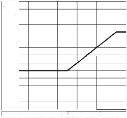
Fig 3.2.1 Longitudinal Distribution Factor for Vertical Design Acceleration
3. The allowable speed corresponding to the design vertical acceleration
may be estimated from
the formulas for the relationship between instantaneous values of and given as
(1) When ≥ 3.0
m s
significant wave height (m ).
:
deadrise angle at LCG (maximum 30° minimum 10°).
: waterline breadth at /2 (m ), for multihull craft, the total breadth of each monohull (exclusive of tunnels) is to be used.
as given in Par 1.
(2) When <
4. Unless other values are justified according to accepted theoretical calculations, model tests or full scale measurements, the speed reductions implied by Par 3 are to be applied. For SWATH and yacht with foil assisted hull, accelerations are normally to be determined in accordance with the di- rect methods above.
![]()
5. Relationships between allowable speed and significant wave height are to be stated in the Appendix to Classification Certificate or drawings.
![]()
203. Horizontal accelerations
1. The longitudinal mula:
(surge) acceleration is not to be less than that obtained from the following for-
: need not be taken greater than 4.0.
: wave coefficient taken from Fig 3.2.2. In cases of yacht having unrestricted area restriction notations, the is to be determined by the formula below. Reduction of for restricted service is taken from Table 3.2.2.
service
0.08
6 + 0.02
: ≤ 100
: m
Class notation | Reduction |
SA0 | 0 |
SA1 | |
SA2 | 10 % |
SA3 | 20 % |
SA4 | 40 % |
SA5 | 60 % |
Table 3.2.2 Reduction of
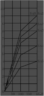
Fig 3.2.2 Wave Coefficient ( )
2. Transverse acceleration is not to be of roll, the static component sin
less than in the formula below. However, when above is to be added.
the axis
: roll period, taken from following formula. However need not be taken as greater than 4.0.
![]()
= maximum roll inclination, taken from the following
rad
: maximum wave height in which 70 % of maximum service speed will be maintained, mini- mum 0.6 .
: height above axis of roll, however, axis of roll is to be taken as given for :
- twinhull yachts : = waterline
- monohull yachts : = 0.5