Iranian Classification Society Rules

< Previous | Contents | Next >
Section 2 Metal Material and Welding
201. Metal material
1. General
(1) The properties of all metal such as steel and aluminium alloy, etc. used in the hull construction and equipment of recreational craft shall be suitable for marine use and the intended methods of construction. However, the requirements not specially provided in this Chapter are to be in ac- cordance with the related requirements in Pt 2, Ch 2 of Rules for the Classification of Steel Ships.
(2) The metal used shall have a suitable finish for the intended application and shall be free from surface defects prejudicial to use for the intended application.
(3) The manufacturer or supplier of the material shall adopt a system of identification, e.g. by col- our coding or stamping, that will enable the material to be traced to its original manufacture.
2. Material combinations
(1) When combining metals of different type or composition, the galvanic potential difference must be considered in order to avoid contact corrosion.
(2) The negative effect on certain timber by adjacent metals and vice versa shall be taken into ac-
count when selecting the materials to be in contact or shall be neutralized, e.g. by shielding or insulation.
3. Steels for hull structure
(1) The steel used for hull structure of recreational crafts is to be mild or higher strength steel in accordance with requirements in Pt 2, Ch 1 of Rules for the Classification of Steel Ships.
(2) Higher
eration not be
strength steel may be used in the construction of craft provided it is taken into consid- that, when fatigue load is present, the effective fatigue strength of a welded joint may
greater than a welded joint in normal strength steels. Where higher strength steel is ap-
plied to the hull structure, the drawings indicating use extent, location, material property and di-
mensions to be submitted to the Society for approval.
(3) Classification for steel used in the hull structure is to be complying with Pt 3, Ch 1, Sec 4
Ch 3 Material Ch 3
![]()
of Rules for the Classification of Steel Ships.
4. Stainless steels
(1) Austenitic stainless steels may be used for construction of recreational craft subject to giving consideration to
(A) the environmental conditions to which the small craft may be subjected,
(B) any intended combination of different metals, the means of insulation from each other and surface protection or coating, and
(C) the detail design to reduce the possibility of pitting and/or crevice corrosion.
(2) This group of steels comprises low-carbon austenitic steels which achieve their resistance to cor- rosion in fresh and sea water by additions of chromium (Cr), nickel (Ni), molybdenum (Mo), and may additionally be stabilized for a stable after welding condition by titanium (Ti) and niobium (Nb).
(3) Alloys suitable for marine use are in general those with a minimum mass fraction of 12 %
chromium and a pitting resistance equivalent (W) exceeding 25
5. Aluminium alloys
(W = % Cr + 3,3 % Mo).
(1) Aluminium alloys used for hull structure of recreational crafts
is to be 5000 or
6000 series in
accordance with requirements in Pt 2, Ch 1 of Rules for the
Classification of Steel Ships.
(2) Alloys of the aluminium-copper group(3000 series) and aluminium-zinc group(7000 series) should
not be used for the construction of recreational crafts. They may be used for secondary pur- poses in recreational craft with special protection, e.g. anodizing, painting.
(3) Aluminium-copper alloys(3000 series) may be used without protection for recreational crafts that
are intended to be used exclusively in fresh water surroundings. It is preferable that they are not of welded construction.
6. Other metals
Structural members of recreational crafts may be built of other metals, e.g. copper- and nick- el- based alloys. Those that are sensitive to crevice corrosion and pitting when not coated shall only be used with cathodic protection when submerged or subject to spray water.
202. Storage and handling
1. Identification and marking
(1) The builder shall establish and maintain a procedure to ensure that material and consumables used in the construction process are identified (by colour-coding and/or marking or any other
means, as appropriate) from arrival in the yard through to fabrication in such a way as to able the type and grade to be readily recognized.
(2) The builder shall maintain purchasing documents containing a clear description of material dered for hull construction referring to the appropriate standards or specifications.
(3) Non-conforming material shall be separated from the acceptable material.
(4) Where materials are found to be defective, they shall be disposed of in accordance with builder´s conformity assurance procedure.
2. Storage
(1) Materials shall be stored in accordance with the material manufacturer’ requirements. Storage
en-
or- the
ar-
rangements shall be such as to prevent deterioration through adverse environmental conditions and poor handling.
(2) Welding consumables shall be stored in suitable conditions to maintain them in accordance with
the material manufacturer’ recommendations.
203. Welding
1. General
(1) The welding in the steels or aluminium alloys used
for hull structure of recreational crafts are
to be suitable for not only 203. of this rule but Pt 2, Ch 2 of Rules for the Classification of Steel Ships.
(2) Details of welded joints for main structural members are to come under construction plan and/or detail drawing.
(3) The welding is to be carried out in accordance with the procedures previously approved with
Ch 3 Material Ch 3
![]()
welding consumables and by the welders qualified by the Society.
2. Preparation
(1) Materials shall be suitably cleaned and cleared of millscale and rust prior to fabrication of the recreational craft.
(2) The preparation of materilas(e.g. cutting, bending and forming) shall follow recognized industry
practice and shall be such as to ensure that the mechanical properties of the material are not adversely affected.
3. Welding work
(1) Adequate protection, such as screening, shall be provided where welding is to carried out in wet, windy or cold weather. In cold or very humid conditions, it may be necessary to preheat the work to prevent too rapid cooling of the weld.
(2) The preparation of plate edges shall be accurate and free from harmful defects. Joints shall be properly fitted up, or aligned without using excessive force, before welding. Parts shall be set up and welded in such a way that contraction stresses are kept to be minimum.
(3) The surfaces to be welded shall be clean, dry and free from grease and other contaminants
which might adversely affect weld quality. Where a primer has been used after surface prepara- tion and prior to fabrication, the composition of the primer shall have no detrimental effect on the subsequent welding work.
4. Quality of welds
(1) The weld is to have a regular and uniform surface and it to be reasonably free from excessive reinforcements, injurious defects, such as undercuts, overlaps, etc.
(2) Welded structures are to be reasonably free from welding deformation.
(3) Non-destructive inspection is to be carried out for welded joints as the Guidance relating to the Rules specified elsewhere.
(4) The welding defects found in an appropriate non-destructive inspection including the visual in- spection or watertight test are to be removed and corrected by rewelding.
5. Repair welding
(1) The removal of weld defects shall be done by gouging, grinding, chipping, etc. with such a manner that the remaining weld metal or base metal is not damaged.
(2) The removed weld defects parts are to be so machined as not to affect repair welding and re-
pair welding shall be carried out with low hydrogen type welding consumables and an electrode preferably smaller than that used for making the original weld.
(3) Members distorted by welding may be straightened by mechanical means or localized heat treat-
ment, however in case of localized heat treatment, the temperature of heated areas is to be so limited as not to affect the mechanical properties of base metal.
204.
Steel/aluminium transition joints
1. Explosion-bonded composite transition joints shall be used for connecting aluminium to steel. These assemblies shall be used in strict compliance with the joint manufacturer´s specification.
2. Bimetallic joints, where exposed to sea water or used internally within wet spaces, shall be suitably protected to prevent galvanic corrosion.
205. Adhesive bonding of structure
1. The adhesive manufacturer´s recommendations in respect to the jointing system, comprising surface preparation, the adhesive, bonding, and curing processes and environmental conditions, shall be strictly followed.
2. Where adhesive bonding of any load-bearing structure is used, test samples shall be manufactured under workshop conditions to demonstrate that the bonded connection develops its intended strength.
3. The method used to bond joints shall be documented so that the process is repeatable after the procedure has been verified.
4. Bonded joints shall be designed to avoid tension on the joints which may cause peeling forces tending to open the joint, unless tests and calculations show that the joint has sufficient strength.
Ch 3 Material Ch 3
![]()
5. Glued joints shall be resistant to, or protected against, sunlight (UV, heat, etc.) and environmental effects or cleaning agents normally encountered in the manufacture or the use of the craft.
206. Steel/wood and aluminium/wood connection
1. To minimize corrosion of steel or aluminium in contact with wood in a damp or marine environ- ment, the surfaces in contact shall be protected in accordance with good practice.
2. Surfaces in contact shall be primed and painted, or coated with a substantial thickness of a suitable sealant.
207. Surface coating
Metal shall be given adequate protection for its intended use by an adequate surface treatment and/or coating, as necessary.
208.
Aluminium craft production, specific requirements
1. General
(1) Aluminium shall not be welded when damp or wet in order to avoid hydrogen inclusions in the welds.
(2) Aluminium shall be stored in dry places, clear of the ground. Contact with other stored materi-
als shall be avoided.
(3) Where a builder is working with both aluminium and steel, the tools directly in contact with the metal used in aluminium production shall be clearly marked(e.g. by colour) for use with aluminium only.
(4) Where bimetallic connections are made, involving dissimilar metals, measures shall be taken to prevent galvanic action.
(5) Areas of the hull structure that are permanently or temporarily submerged shall be protected by means of coating or cathodic protection.
(6) The welding in the aluminium alloys used for hull structure of recreational crafts are to be in accordance with 2 to 6. Any contents other than those specified in 2 to 6 are to be in accord-
ance with Pt 2, Ch 2 of Rules for the Classification of Steel Ships.
2. Groove design
(1) The groove design of welded connections, as a rule, is to be in accordance with Table 3.1.
Grooves and root gaps which differ from these may be subject to special consideration.
(2) To minimize distortion, the X groove with the narrowest root gap practicable is recommended for thick material, instead of single-V groove.
3. Welding consumables
Welding consumables used for aluminium alloys is to be applied in accordance with Table 3.2.
Ch 3 Material Ch 3
![]()
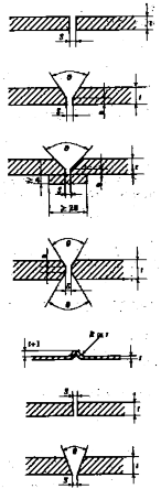
Table 3.1 Groove Design of TIG and MIG Welding
Groove design | Dimension | Remarks | |||
MIG | Ź Z | = = | 1.5 ~ 5 0 ~ 2 | Welding from one side. Backing may be used. | |
Ź Z Ŵ P | = = = = | 5 ~ 25 0 ~ 3 1.5 ~ 3 60 ~ 100° | Largest angle is recommended for under-up position. Back chipping and rewelding should be carried out. | ||
Ź Z Ŵ P | = = = = | 8 ~ 25 3 ~ 7 2 ~ 4 40 ~ 60° | Smallest joint angle may be used up to 15 mm and with the largest root gap. Position vertical, un- der-up and side-in require large root gap. | ||
Ź | = | 12 ~ 25 | Allowed specially for automatic welding. | ||
Z | = | 0 ~ 2 | Semiautomatic processes may be used in all posi- | ||
Ŵ | = | 3 ~ 5 | tions, and shall be back chipped before welding | ||
P | = | 50 ~ 70° | from backside. | ||
TIG | Ź | ≤ | 2 | ||
Ź Z | ≤ = | 4 0 ~ 2 | Welding from one side. | ||
Ź Z P | = = = | 4 ~ 10 0 ~ 2 60 ~ 70° | Backing may be used in horizontal position | ||
Ź = material thickness (mm ) Ŵ = root face (mm ) Z = root gap (mm ) P = joint angle | |||||
![]()
Table 3.2 Application of Welding Consumables used for Aluminium Alloy
Kind and grade of aluminium alloys to be welded | Grade of applicable welding consumables | |
5000 seriesFËF | 5754 P | RAlRA, RAlRB, RAlRC RAlW A, RAlW B, RAlW C |
5086 P, 5086 S | RAlRB, RAlRC RAlW B, RAlW C | |
5083 P, 5083 S | RAlRC, RAlW C | |
6000 seriesFËF | 6005 AS | RAlRD , RAlW D |
6061 P, 6061 S | RAlRD , RAlW D | |
6082 S | RAlRD , RAlW D | |
(NOTES) (1) For welded joint of 5000 series alloys and 6000 series, the welding consumables corresponding to 5000 series alloys specified in this table may be used. | ||
Ch 3 Material Ch 3
![]()
4. Preparation for welding
(1) Edge preparation
(A) Proper edge preparation is to be employed.
(B) Joint edge may be prepared by mechanical cutting, such as band sawing, and by plasma (TIG) arc cutting.
(2) Cleanliness
(A) All oil or other hydrocarbons, paint and loose particles from the sawed edges must be re- moved prior to welding.
(B) Oil or grease films may be removed chemically by dipping, spraying or wiping the alumi- nium plate with solvents. Mildly alkaline solutions may be used for cleaning and all weld- ing surfaces shall be thoroughly dried before welding.
(C) Oxide films, which will prevent fusion between the filler metal and the parent material are to be removed from the weld bevels and a minimum of 75 mm to any side, prior to
assembly. Mechanical means, such as a power-driven clean, stainless steel brush, or suitable chemical means are to be used. Welding is to take place immediately after cleaning, and the welding site is to be protected against draft, wind and moisture.
(3) Backing
(A) When backing is used, the joint angle is to be large enough to provide accessibility for the root runs.
(B) Besides aluminium alloys, stainless steel and copper may be used as backing bar material.
(C) When copper backing is used, copper pickup is to be prevented because local deposition can result in corrosion service.
(D) Temporary aluminium backing is to be removed by chipping after welding. If the butt weld is not completely fused to the temporary aluminium backing, the root pass is to be back
chipped to sound metal after the backing bar has been removed.
(E) When permanent aluminium backing is used, it is necessary to obtain complete fusion be- tween the backing, the root faces and the root layer of the weld. Permanent backing is not recommended where crevice corrosion is of a concern. In these conditions, all edges of the backing bars are to be completely welded.
5. Main welding
(1) The welding process may be manual, semi-automatic or automatic according to welding proce- dure specifications.
(2) TIG-welding is a recommended process for welding of thinner MIG-welding is recommended for thicker gages.
(3) For MIG fillet welds, back stepping is recommended to fully
eliminate cracking problems that usually accompany the crater.
(4) Other welding methods such as resistance, spot, seam, stud or
gages and precision weldments. fill the end crater and thereby
electron beam welding may be
approved by the Society after consideration in each separate case.
6. Preheating
(1) Plorwehe5at℃ingoor fwphaernts thtoe bmeasws eoldfedtheisptaortsbeis csaurcrihedthoaut t thwehehneathies tceomnpdeurcatteudreawofaythferopmarttsheisjobine-t faster than the welding process can supply it. Use of preheat is required when welding is per- formed under high humidity conditions.
(2) The preheating temperature must be limited to maximum 60 ℃, due to the increased suscepti-
bility of stress corrosion cracking for 5000 series alloys above this temperature.
Acceptance criteria fabrication
7.
(1) Visual inspection
(A) All welds are to show good workmanship with smooth transition to the base material with- out sharp edges. An overlap or deficient weld is not acceptable.
(B) For butt welds, weld reinforcement or excessive penetration is not to exceed 2 mm .
(C) For fillet and partial penetration welds, weld reinforcement is not to exceed 3 mm .
(D) For throat thickness, a negative deviation from that which is specified is not
(E) The difference in leg lengths of a fillet weld is not to exceed 3 mm .
(2) Non-destructive examination
(A) Requirements for non-destructive examination to be complying with Pt 2,
Guidance for the Classification of Steel Ships.
![]()
(B) Cracks, incomplete penetration and lack of fusion are not acceptable.
allowed.
Annex 2-7 of
Ch 3 Material Ch 3
![]()