Iranian Classification Society Rules

< Previous | Contents | Next >
driven steering systems are to be in accordance with the requirements of ISO 13929.
Section 2 Hydraulic Steering System
201. General requirements for hydraulic steering systems
1. The components of hydraulic steering systems are to be compatible with each other in order to be used as a complete system.
2. All component parts are to be supported independently of the connecting tubes.
3. Connections, fittings, oil fill openings
4. Components in the system are to be steering system is to be designed movement without failure or leakage.
and air bleeders are to be readily accessible.
externally protected against corrosion. The complete hydraulic to withstand conditions of pressure, vibration, shock and
5. aHmydbrieanutlictemsypseteramtusrewriathngea onfon--1f0un℃ctiotnoal+6a0ut℃opilaontd abree ctoapabbelecaopfabwleithostfanodpinegratsiotonragtehraotug-3h0ou℃t
+60 ℃.
taon
6. Fittings, hoses, piping and components are to be capable of withstanding the system test pressure without permanent deformation, external leakage or other malfunction.
7. Materials used in hydraulic steering systems are to be resistant to deterioration by liquids or com- pounds with which the material may come in contact under normal marine service, e.g. grease, lu- bricating oil, hydraulic fluid, common bilge solvents, salt and fresh water.
8. In vessels over 12.5 m in length, the hydraulic steering system is to be capable of putting the rud- der over from 30° on one side to 30° on the other in not more than 30 s when the vessel is at maximum forward service speed with the rudder totally submerged, and, if normally operated, is to be designed to prevent violent recoil of the steering-wheel.
202. Hydraulic fluid
1. The type of hydraulic fluid to be used in a hydraulic steering system is to be specified by the manufacturer of the steering system and is to be stated in the owner's manual.
2. The hydraulic fluid is to be non-flammable or have a flash point of 157 °C or over.
203. Materials
In addition to the general requirements of 201., the following requirements are to be met.
1. Components of different materials are to be galvanically compatible or separated by a galvanic
Ch 7 Steering System Ch 7
![]()
2.
3.
204.
1.
barrier.
Plastics and elastomers which may be exposed to sunlight are to be chosen to resist degradation by ultraviolet radiation.
Plastics and elastomers which may be installed in engine compartments are to be chosen to resist degradation by saline atmospheres, fuel. oil, heat and fire.
Outboard non-sailing and inboard-outdrive requirements
Steering stops on an outboard non-sailing is to permit at least 30° of angular movement to either side. The design torque at the rudder stock is to be sufficient to put the helm from hard over to hard over (30° port to 30° starboard or vice versa) in not more than 30 s.
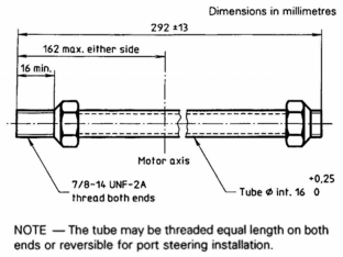
2. Outboard non-sailings are to meet the applicable dimensional requirements indicated in Fig 7.1 and
Fig 7.2.
3. Necessary fittings to attach an outboard non-sailing to the cylinder output rod are to be supplied with the outboard non-sailing.
4. Outboard non-sailings are to be designed so that with any combination of non-sailing turn and tilt, there are to be no damaging interference between the non-sailing, its accessories, and both the craft- mounted and the non-sailing-mounted system, if the non-sailing is designed for both systems. Appropriate written information and installation instructions are to be provided, clearly indicating the type of steering system(s) that should be used.
5. Outboard non-sailings are to be designed so that the geometry ensures that a static force of 3,300 N, applied at the steering arm connection point normal to the steering arm in its normal plane of operation throughout the maximum steering arc, will not result in steering output ram loadings greater than those specified in 206.
6. The steering arm of an outboard non-sailing is to be provided with a 3/8 in-24 UNF thread, or a plain hole of 9.65 mm to 9.9 mm diameter at the connection point.
7. Inboard-outdrives are to be designed with proper geometry to ensure that a torque of 680 Nm
applied on the outdrive specified in 206.
steering axis will not result in a steering component loading greater that
Fig 7.1 Non-sailing-mounted steering tube
Ch 7 Steering System Ch 7
![]()
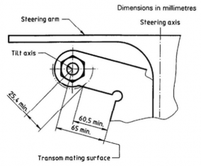
Fig 7.2 non-sailing-mounted steering tilt axis
205.
1.
Installation
The installation Hydraulic lines
is to be carried out following the directions of the manufacturers of the system. are to be supported by clips, straps or other means to prevent chafing or vibration
damage. The clips, straps or other devices are to be corrosion-resistant and are to be designed to
prevent cutting, abrading or damage to the lines and are to be compatible with hydraulic line materials. A flexible section is to be installed between rigid piping and cylinder(s).
2. Hoses and piping are to be protected from contact with hot objects and from abrasion. There are to be no joints or connections directly above hot objects.
3. Hydraulic components are to be secured to the craft's structure considering the potential forces to be transmitted. Specifically, the mounting location for hydraulic cylinders is to provide a rigid attachment.
4. All threaded fasteners whose integrity affects safe operation of the hydraulic steering system are to be provided with a locking means.
5. Steering wheels and helm shafts are to be selected to fit each other. Current configurations are shown in Fig 7.3.
6. Threaded fasteners whose integrity affects safe operation of the steering system, and which are intended to be mounted or adjusted at the installation of the steering system in the craft and which may be expected to be disturbed by installation or adjustment procedures, are to be locked by locking devices referenced by instructions for correct assembly and complying with the following requirements.
(1) Loose lock-washers. fasteners with metallic distorting threads and adhesive are prohibited.
(2) A locking device is to be so designed that its presence can be determined by visual inspection or felt by a layman after installation.
Ch 7 Steering System Ch 7
![]()
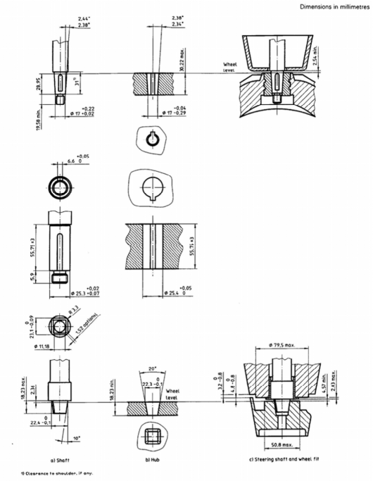
Fig 7.3 Steering shafts and steering-wheel hubs
206. Tests
Hydraulic steering systems are to subject to tests in accordance with 9. in ISO 10592 to verify the design strength and to verify that components are meet with minimum acceptable design criteria.
207. Manual and marking
1. An owner's manual and an installer's manual are to include the information in accordance with 10 and 11 in ISO 10592.
Ch 7 Steering System Ch 7
![]()
2. Hydraulic steering systems are to provided with marking in accordance with 12 in ISO 10592 and components are to proded with marking in accordance with 13 in ISO 10592.