Iranian Classification Society Rules

< Previous | Contents | Next >
Section 1 Fire Protection
101. Arrangement and design of craft
1. The type of equipment installed and the layout of the craft are to take account of the risk and spread of fire. Special attention is to be paid to the surroundings of open flame devices, hot areas or engines and auxiliary machines, oil and fuel overflows, uncovered oil and fuel pipes and avoid- ing electrical wiring above hot areas of machines.
2. Materials used for the insulation of engine space are to be of non-combustible and are to comply with the requirements of 4.5.2 in ISO 9094-2.
3. Bilges that may contain spillage of flammable liquids are to be accessible for cleaning.
4. Components containing petrol/gasoline engines and/or petrol/gasoline tanks are to be separated from enclosed accommodation spaces. The condition is met if the structure fulfills the following require- ments:
(1) The boundaries are to be continuously sealed.(e.g. welded, brazed, glued, laminated or otherwise sealed)
(2) Penetrations for cables, piping, etc. are to be closed by fittings, seals and/or sealants.
(3) Access openings, such as doors, hatches, etc., are to be equipped with fittings so that they can be secured in the closed position.
5. Petrol/gasoline tanks within an engine room are to be insulated from the engine or any other source of heat by either.
(1) a physical barrier between the tank and engine, engine-mounted components including fuel-and water-supply lines, and any source of heat (e.g. bulkhead, wall, insulating material, etc.), or
(2) an air gap to prevent any contact between the tank and engine, and engine-related components,
and any source of heat, the gap being wide enough to allow for servicing the engine and its related components. The air gap is to be at least;
(A) 100 mm between a petrol engine and a fuel tank, and
(B) 250 mm between a dry exhaust and a fuel tank.
6. Passages through accommodation spaces are not to be obstructed.
7. Where a non-metallic flexible hose is part of a water-cooled exhaust system, an alarm at the main steering position is to be activated if there is a loss of cooling water or if the temperature inside the exhaust line surpasses a preset limit(craft with a length of over 15 m).
102. Escape routes and exits
1. Escape routes
(1) Escape routes for crafts with a length of up to and including 15 m are to comply with the following.
(A) The distance to the nearest exit to the open air is not to exceed 5 m.
(B) Where the exit route passes beside an engine space, the distance to the nearest exit is not to exceed 4 m.
(C) The distance is to be measured in the horizontal plane as the shortest distance between the
centre of the exit and following point, and whichever is to be the greater distance.
- the farthest point where a person can stand (minimum height 1.60 m), or
- the midpoint of a berth
(D) Where only one escape route is provided, this is not to pass directly over a cooker.
(E) Where living or sleeping accommodation is separated from the nearest exit by a solid parti- tion (e.g. a door) and leads directly past a cooker or engine space, an alternative exit is to
be provided.
(2) Escape routes for crafts with a length of over 15 m are to comply with the following.
(A) The following requirements are to be met irrespective of the accommodation arrangement.
(a) Where there are two escape routes, only one may pass through, over and beside an en-
Ch 11 Fire Protection and Fire Extinction Ch 11
![]()
gine space.
(b) Where the distance between a cooking or open-flame heating-appliance burner and the nearest side of an escape route is less than 750 mm, a second escape route is to be provided. In an enclosed galley, this requirement does not apply where the dead end be- yond the cooker is less than 2 m.
(c) No escape route is to pass directly over a cooking or open-flame heating appliance.
(B) Open-accommodation arrangement
Where living or sleeping accommodation is not separated from the nearest exit, i.e. people can move around without passing through any door, the following is to apply(Doors of toi- let or shower compartments are disregarded.).
(a) The distance to the nearest exit is not to exceed (ÄĂ /3) m.
(b) The distance is to be measured in the horizontal plane as the shortest distance between
the center of the exit and following point, and whichever is to be the greater distance.
- the farthest point where a person can stand (minimum height 1.60 m), or
- the midpoint of a berth
(C) Enclosed accommodation arrangement
Where living or sleeping accommodation is separated from the nearest main exit by bulk- heads and doors, escape routes and exits from accommodation areas are to be arranged to
reduce the risk of people being trapped and the following conditions are to be met.
(a) Each accommodation section is to have more than one escape route leading finally to
the open air, unless it is a single cabin or compartment intended to accommodate no
more than
four persons and the exit leads directly to the open air without passing
through or over engine spaces or over cooking appliances. The cabin must not contain open-
cooking or flame heating devices.
(b) For individual cabins intended to accommodate no more than four persons, and not con- taining cooking or open-flame heating devices, escape routes may form shared escape ways for up to 2 m, measured to a two-way escape route from the door or entrance.
(c)
Shower and toilet compartments are regarded as part of the compartment or passageway that gives access to their doors and therefore do not require alternative escape routes.
2. Exits
(d) With multi-level arrangements, the exits are to lead to a different accommodation section or compartment, as far as practicable.
Fig 11.1 shows a typical cabin arrangement of a big non-sailing yacht. According to the conditions specified above, this section of the craft requires two exits, because the shared route from cabins C and D is longer than 2 m. In this case, the two exits are the main staircase (primary exit) and a deck hatch between cabins C and D (secondary
exit).
(1) Any exit from an accommodation space or from any other space is to have the following mini- mum clear openings:
(A) Circular shape : diameter 450 mm;
(B) Any other shape : minimum dimension of 380 mm and minimum area 0.18 mË. The exit is to be large enough to allow for a 380 mm diameter circle to be inscribed. The measure- ment of the minimum clear opening is illustrated in Fig 11.2.
(2) Exits are to be readily accessible. Exits leading to the weather deck or to the open air are to be capable of being opened from the inside and outside when secured and unlocked. The re- quirement does not apply to port-lights of sufficient size to be designated as exits.
(3) Where deck hatches are designated as exits, footholds, ladders, steps or other means are to be provided. The vertical distance between the upper foothold and the exit is not to exceed 1.2 m.
(4) Escape facilities or doors are to be identified by the appropriate ISO or national symbol.
Ch 11 Fire Protection and Fire Extinction Ch 11
![]()
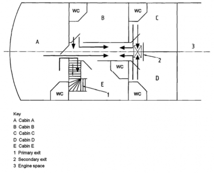
Fig 11.1 Escape routes and exits
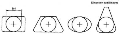
Fig 11.2 Measurement of minimum clear opening
103. Cooking and heating appliances
1. Where flues are installed, they are to be insulated or shielded to avoid overheating or damage to adjacent material or to the structure of the craft.
2. For cooking and heating units using fuel which is liquid at atmospheric pressure, the following are to apply.
(1) Stoves and heating units are to be securely fastened.
(2) Open-flame burners are to be fitted with a readily accessible drip-pan.
(3) Where open-flame-type water heaters are installed, adequate ventilation and flue protection are to be provided.
(4) Where a pilot light is installed, the combustion chamber is to be room sealed, except for
cookers.
(5) Appliances using petrol for priming, or as a fuel, are not to be installed.
(6) For non-integral tanks and supply lines, the following are to be met.
(A) Non-integral tanks are to be securely fastened and are to be installed at a sufficient distance from cooking and heating units.
(B) A readily accessible shut-off valve is to be installed on the tank. If this is outside the gal-
ley, a second valve is to be fitted in the fuel line in the galley space. This requirement does not apply where the tank is located lower than the cooker/heater and there is no possi- bility of back siphoning.
Ch 11 Fire Protection and Fire Extinction Ch 11
![]()
3. Materials used in the vicinity of cooking and heating devices are to be in accordance with 4.3.1 of ISO 9094-1(crafts with a length of up to and including 15m) or 4.4.1 of 9094-2(crafts with a length of up to and including 15m).