Iranian Classification Society Rules

< Previous | Contents | Next >
Section 6 Materials of Construction
601.
General
1. This Section gives the requirements for plates, sections, pipes, forgings and castings, etc. used in the construction of cargo tanks, cargo process pressure vessels, cargo and process piping and con- tiguous hull structures associated with the transportation of the products.
2. The manufacture, testing, inspection and documentation are to be in accordance with the require- ments of Pt 2 of the Rules and the specified requirements given in this Section.
3. The composite materials or hybrid(metallic/composite) materials may be used where specially ap- proved in connection with the design. In such cases, the detailed data relating to the manufacturing process, chemical compositions and mechanical properties, etc. of the materials are to be submitted for approval.
4. In case where deemed necessary by the Society in connection with the design temperature and de- sign pressure of the materials, following data may additionally be required.
(1) Fracture toughness
(2) Strain-aged mechanical properties (tensile and impact)
(3) Fatigue
(4) Corrosion and Corrosion Fatigue
(5) Weldability
602.
Base material
1. The requirements for rolled materials, forgings and castings are given in Tables 3.6.1 to 3.6.5.
However, materials by the Society.
with alternative chemical composition or mechanical properties may be accepted
![]()
Table 3.6.1
PLATES, PIPES (SEAMLESS AND WELDED) , SECTIONS AND FORGINGS FOR CARGO TANKS AND PROCESS PRESSURE VESSELS FOR DESIGN TEMPERATURES NOT LOWER THAN 0°C. |
CHEMICAL COMPOSITION AND HEAT TREATMENT CARBON-MANGANESE STEEL, Fully killed Fine grain steel where thickness exceeds 20 mm Small additions of alloying elements by agreement with the Society Composition limits to be approved by the Society Normalized, or quenched and tempered |
TENSILE AND TOUGHNESS (IMPACT) TEST REQUIREMENTS Plates Each "piece" to be tested Sections and forgings Batch test Tensile properties Specified minimum yield stress not to exceed 410 N mm CHARPY V-NOTCH TEST Plates Transverse test pieces. Minimum average energy value (E) 27 Sections and forgings Longitudinal test pieces. Minimum average energy value (E) 41 Test temperature
Thickness (mm ) Test temperature(°C)
≤20 0 20< ≤40 -20 |
Notes: (1) For seamless pipes and fittings are to be in accordance with Pt 2 of the Rules. The use of longitudinally and spirally welded pipes is to be specially approved by the Society. (2) A thermo-mechanical controlled rolling process or a controlled rolling procedure may be used as an alter- native to normalizing or quenching and tempering, subject to special approval by the Society. (3) Materials with specified minimum yield stress exceeding 410 N mm may be specially approved by the Society. For these materials, particular attention should be given to the hardness of the weld and heat af- fected zone. |
![]()
![]()


Table 3.6.2
PLATES, SECTIONS AND FORGINGS FOR CARGO TANKS AND PROCESS PRESSURE VESSELS FOR |
CHEMICAL COMPOSITION AND HEAT TREATMENT CARBON-MANGANESE STEEL, Fully killed, Aluminium treated fine grain steel Chemical composition (ladle analysis)
C Mn Si S P 0.16 % max 0.70~ 1.60 % 0.10~ 0.50 % 0.035 % max 0.035 % max Optional additions: Alloys and grain refining elements may be generally in accordance with the following: Ni Cr Mo Cu Nb V
0.8 % max. 0.25 % max. 0.08 % max. 0.35% max. 0.05 % max. 0.10 % max.
Normalized or quenched and tempered |
TENSILE AND TOUGHNESS (IMPACT) TEST REQUIREMENTS Plates Each "piece" to be tested Sections and forgings Batch test CHARPY V-NOTCH TEST Test temperature 5°C below the design temperature or -20°C whichever is lower Plates Transverse test pieces. Minimum average energy value (E) 27 Sections and forgings Longitudinal test pieces. Minimum average energy value (E) |
Notes: (1) The Charpy V-notch and chemistry requirements for forgings may be specially considered by the Society. (2) For material thickness of more than 25 mm, Charpy V-notch tests is to be conducted as follows:
Material thickness (mm ) Test temperature
25< ≤30 10°C below design temperature or -20°C whichever is lower 30< ≤35 15°C below design temperature or -20°C whichever is lower 35< ≤40 20°C below design temperature The impact energy value is to be in accordance with the table for the applicable type of test specimen. For material thickness of more than 40 mm, the Charpy V-notch values is to be specially considered. Materials for tanks and parts of tanks which are completely thermally stress relieved after welding may be tested at a tem- perature 5°C below design temperature or -20°C whichever is lower. For thermally stress relieved reinforce- ments and other fittings, the test temperature is to be the same as that required for the adjacent tank-shell thickness. (3) By special agreement with the Society, the carbon content may be increased to 0.18 % maximum provided the design temperature is not lower than -40°C. (4) A thermo-mechanical controlled rolling process or a controlled rolling procedure may be used as an alternative to normalizing or quenching and tempering, subject to special approval by the Society. Guidance: For materials exceeding 25 mm in thickness for which the test temperature is -60°C or lower, the ap- plication of specially treated steels or steels in accordance with Table 3.6.3 may be necessary. |
![]()
![]()
Table 3.6.3
PLATES, SECTIONS AND FORGINGS FOR CARGO TANKS AND PROCESS PRESSURE VESSELS FOR | ||
Minimum de- sign temp. (°C) | Chemical composition and heat treatment | Impact test temp (°C) |
-60 | 1.5 % nickel steel-normalized | -65 |
-65 | 2.25 % nickel steel-normalized or normalized and tempered(4) | -70 |
-90 | 3.5 % nickel steel-normalized or normalized and tempered(4) | -95 |
TENSILE AND TOUGHNESS (IMPACT) TEST REQUIREMENTS Plates Each "piece" to be tested Sections and forgings Batch test CHARPY V-NOTCH TEST Plates Transverse test pieces. Minimum average energy value (E) 27 Sections and forgings Longitudinal test pieces. Minimum average energy value (E) 41 | ||
Notes: (1) The impact test required for forgings used in critical applications is to be subject to special consideration by the Society. (2) For materials 1.5 % Ni, 2.25 % Ni and 3.5 % Ni, with thicknesses greater than 25 mm, the impact tests is to be conducted as follows:
Material thickness (mm ) Test temperature 25< ≤30 10°C below design temperature 30< ≤35 15°C below design temperature 35< ≤40 20°C below design temperature In no case is the test temperature to be above that indicated in this table. The energy value is to be in ac- cordance with this table for the applicable type of test specimen. For material thickness of more than 40 mm, the Charpy V-notch values are to be specially considered. (3) The chemical composition limits are to be approved by the Society. (4) A lower minimum design temperature for quenched and tempered steels may be specially agreed with the Society. | ||
![]()
Table 3.6.4
PIPES (SEAMLESS AND WELDED) , FORGINGS AND CASTINGS FOR CARGO AND PROCESS | |||
Minimum de- sign temp. (°C) | Chemical composition and heat treatment | Impact test | |
Test temp.(°C) | Minimum aver- age energy ( )(J ) | ||
-55 | Carbon-manganese steel. Fully killed fine grain. Normalized or as agreed | 27 | |
-65 | 2.25 % nickel steel. Normalized or normalized and tempered | -70 | 34 |
-90 | 3.5 % nickel steel. Normalized or normalized and tempered | -95 | 34 |
TENSILE AND TOUGHNESS (IMPACT) TEST REQUIREMENTS Each batch to be tested IMPACT TEST : Longitudinal test pieces | |||
Notes: (1) The use of longitudinally or spirally welded pipes is to be specially approved by the Society. (2) The requirements for forgings and castings may be subject to special consideration by the Society. (3) The test temperature should be 5°C below the design temperature or -20°C whichever is lower. (4) The composition limits are to approved by the Society. (5) A lower design temperature may be specially agreed with the Society for quenched and tempered materials. (6) The impact test for stainless steel is to be as belows; (A) In general, impact tests are not required for forgings, rolled products and seamless pipes in stainless austenitic steel of grades 304, 304L, 316, 316L, 321 and 347. (B) Impact tests are required for castings in steel grades 304, 304L, 321 and 347 when the service temper- ature is below -60°C (C) Impact tests are required for castings in steel grades 316 and 316L (which contain molybdenum) at any temperature. A reduction of the tests may be granted for design temperatures above -60°C after exami- nation of each case by the Society. | |||
![]()
Table 3.6.5
PLATES AND SECTIONS FOR HULL STRUCTURES REQUIRED BY 408. 1 AND 408. 3 | |||||||
Minimum design temperature of hull structure(°C) | Maximum thickness (mm) for steel grades | ||||||
A | B | D | E | AH | DH | EH | |
0 and above | -5 and above | Normal practice | |||||
down to -5 | 15 | 25 | 30 | 50 | 25 | 45 | 50 |
down to -10 | × | 20 | 25 | 50 | 20 | 40 | 50 |
down to -20 | × | × | 20 | 50 | × | 30 | 50 |
down to -30 | × | × | × | 40 | × | 20 | 40 |
Below -30 | In accordance with Table 3.6.2 except that the thickness limitation giv- en in Table 3.6.2 and in footnote (2) of that table does not apply. | ||||||
Notes: "x" means steel grade not to be used. (1) For the purpose of 408. 3 (2) For the purpose of 408. 1 (3) Where reference is made in this Section to A, B, D, E, AH, DH and EH hull structural steels, these steel grades are the grades of steel according to Pt 2 of the Rules. | |||||||
![]()
2. Chemical composition
(1) The carbon equivalent, Ceq for the steel is not to exceed 0.48.
(2) The cold cracking susceptibility, Pcm value for the steel is not to exceed 0.22.
(3) The
carbon equivalent, Ceq, and the cold cracking susceptibility, Pcm, are to be calculated ac-
cording to Pt 2 of the Rules.
3. Tensile strength, yield stress and elongation are to be to the satisfaction of the Society. For car- bon- manganese steel and other materials with definitive yield points, consideration are to be given to the limitation of the yield to tensile ratio.
4. Impact test
(1) Acceptance tests is to include Charpy V-notch toughness tests unless otherwise specified by the Society. The specified Charpy V-notch requirements are minimum average energy values for three full size (10 mm × 10 mm) specimens and minimum single energy values for individual specimens.
(2) Dimensions and tolerances of Charpy V-notch specimens are to be in accordance with the re-
quirements in Pt 2 of the Rules. The testing and requirements for specimens smaller than mm size are to be in accordance with the Recognized Standards.
(3) Minimum average values for sub-sized specimens are to be:
5.0
Charpy V-notch specimen size | Minimum energy average of three specimens |
10 x 10 m m 10 x 7.5 mm 10 x 5.0 mm | 5/6 2/3 |
where: = the energy values ( ) specified in Tables 3.6.1 to 3.6.4
![]()
(4) Only one individual value may be below the specified average value provided it is not than 70 % of that value.
(5) In all cases, the largest size Charpy specimens possible for the material thickness is to be
less
ma-
chined with the specimens located as near as practicable to a point midway between the surface
and the centre of the thickness and the length of the notch perpendicular to the suface (see Fig 3.6.1).
(6) Where the result of the impact test is unsatisfactory, additional tests may be carried out, with the exception of the cases specified in (A) and (B) below, by taking a set of test specimens
out of the same piece from which the above-mentioned test specimens have been taken.
(A) The absorbed energy of all test specimens is under the required average absorbed energy.
(B) The absorbed energy of two of the test specimens is under 70 % the required average ab- sorbed energy.
(7) In case of the previous (6), all pieces of the same lot from which the test specimens have been taken, may be accepted, provided that the average absorbed energy of the six test specimens, including those which have been rejected as unsatisfactory, is not less than the required average
absorbed energy, and that not more than two individual results are lower than the required aver- age absorbed energy and of these, not more than one result is below 70 % of the required aver- age absorbed energy.
(8) At the discretion of the Society other types of toughness tests, such as a drop weight test, may be used. This may be in addition to or in lieu of the Charpy V-notch test.
5. Where post-weld heat treatment is specified or required, the properties of the base material are to be determined in the heat treated condition in accordance with the applicable table of this Section and the weld properties are to be determined in the heat treated condition in accordance with 603. In cas- es where a post-weld heat treatment is applied, the test requirements may be modified at the dis- cretion of the Society.
![]()
6. All plate materials used in the manufacturing of pipes, end plate and nozzles for CNG cargo tanks are to be subjected to 100 % surface and volumetric ultrasonic examination. Ultrasonic test procedures and acceptance criteria are to be in accordance with either EN 10160 Level S1/E1, ASTM A 578 Level C or accepted standard at the discretion of the Society.
![]()
603.
Welding and non-destructive testing
1. General
The requirements of this Article are those generally employed for welding of carbon, car- bon- managanese, nickel alloy and stainless steels, and may form the basis for acceptance testing of other material. At the discretion of the Society, impact testing of stainless steel weldments may be omitted and other tests may be specially required for any material.
2. Welding consumables are to be approved in accordance with the requirements of Pt 2 of the Rules.
3. Welding procedure tests for cargo tanks and process pressure vessels
(1) Welding procedure tests for cargo tanks and process pressure vessels are required for all butt welds and the test assemblies are to be representative of:
- each base material
- each type of consumable and welding process
- each welding position.
For butt welds in plates, the test assemblies are to be so prepared that the rolling direction is
parallel to the direction of welding. The range of thickness qualified by each welding procedure test is to be in accordance with Recognized Standards. Radiographic or ultrasonic testing may
be performed at the option of the fabricator or the Society. Procedure tests for consumables in-
tended for fillet welding procedure tests are to be in accordance with Recognized Standards. In
such cases consumables are to be
(2) The following welding procedure made from each test assembly:
(A) Cross-weld tensile tests.
(B) Transverse bend tests which Society. However, longitudinal
selected which exhibit satisfactory impact properties.
tests for cargo tanks and process pressure vessels are to be
may be face, root or side bends at the discretion of the bend test may be required in lieu of transverse bend tests in
cases where the base material and weld metal have different strength levels.
(C) One set of three Charpy V-notch impacts, generally at each of the following locations, as shown in Fig 3.6.1:
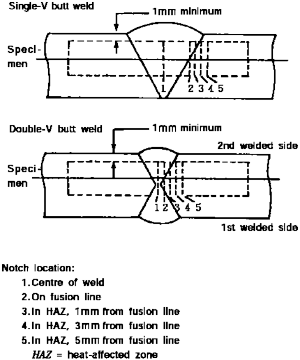
Fig 3.6.1 Orientation of Weld Test Specimen
![]()
(D) Macrosection, microsection and hardness survey may also be required by the Society.
4. Test requirements
(1) Tensile tests
(A) In general, tensile strength is not to be less than the specified minimum tensile strength for the appropriate parent materials.
(B) The Society may also require that the transverse weld tensile strength is not to be less than the specified minimum tensile strength for the weld metal, where the weld metal has a low-
er tensile strength than that of the parent metal.
(C) In every case, the position of fracture is to be reported for information.
(2) Bend tests: No fracture is acceptable after a 180° bend over a former of a diameter 4 times the thickness of the test pieces, unless otherwise specially required by or agreed with the Society.
(3) Charpy V-notch impact tests:
(A) Charpy tests are to be conducted at the temperature prescribed for the base material being joined.
(B) The results of weld metal impact tests, minimum average energy (E), is to be no less than 27J. The weld metal requirements for sub-size specimens and single energy values are to be in accordance with 602. 4.
(C) The results of fusion line and heat affected zone impact tests are to show a minimum aver- age energy (E) in accordance with the transverse or longitudinal requirements of the base
material, whichever is applicable, and for sub-size specimens, the minimum average energy
(E) is to be in accordance with 602. 4.
(D) If the material thickness does not permit machining either full-size or standard sub-size
specimens, the testing procedure and acceptance standards are to be in accordance with Recognized Standards.
5. Welding procedure tests for piping
Welding procedure tests for piping is to be carried out and is to be similar to those detailed for cargo tanks in Par 3. Unless otherwise specially agreed with the Society, the test requirements are to be in accordance with Par 4.
6. Production weld tests
(1) For all cargo tanks and process pressure vessels production weld tests should generally be per- formed for approximately each 50 m of butt weld joints and should be representative of each welding position. Tests, other than those specified in (2), may be required for cargo tanks at the discretion of the Society.
(2) The production tests for all cargo tanks and process pressure vessels are tod include the follow- ing tests:
(A) Bend tests, and where required for procedure tests one set of three Charpy V-notch tests are to be made for each 50 m of weld. The Charpy V-notch tests atr to be made with speci-
mens having the notch alternately located in the centre of the weld and in the heat affected
zone (most critical location based on procedure qualification results). For austenitic stainless steel, all notches are to be in the centre of the weld.
(B) The test requirements are the same as the applicable test requirements listed in Par 4, that
impact tests
that do not meet the prescribed energy requirements may still be accepted,
upon special consideration by the Society, by passing a drop weight test. In such cases, two
drop weight
specimens are to be tested for each set of Charpy specimens thatfailed and
both must show "no break" performance at the temperature at which the Charpy tests were conducted.
(C) In addition to those tests listed in (A) transverse weld tensile tests are required. The test re- quirements are listed in Par 4 except that impact tests that do not meet the prescribed en-
ergy requirements may still be accepted upon special consideration by the Society, by pass-
ing a drop weight test. In such cases, two drop weight specimens are to be tested for each set of Charpy specimens that failed, and both must show "no break" performance at the temperature at which the Charpy tests were conducted.
7. Production weld tests
(1) Inspection of cargo tanks and process pressure vessels is to be carried out in accordance with
409. 5.
(2) Inspection of piping is to be carried out in accordance with the requirements of Sec 5.
![]()


