Iranian Classification Society Rules

< Previous | Contents | Next >
ANNEX 2 Test and Inspection of Sandwich Constructions Materials
1. Manufacturing methods of test laminates for sandwich constructions
(1) One each of test laminates of sandwich construction which are of the same laminate composi- tion and the same mouldiprocedures as those for bottom laminates, side shell laminates and up- per deck laminates is to be manufactured. However, when either of the bottom laminates, side shell laminates or upper deck laminates has the same laminate composition with the other, one test laminate may be manufactured for those of the same laminate composition.
(2) The size of the test laminates is to be sufficient to cut all the test specimens specified in the following 2. and 3.
2. The selection of test specimens
(1) The tensile test specimens and bending test specimens are to be cut laminates clearing 60mm belt from the periphery.(See Fig 2.1)
alternately from the test
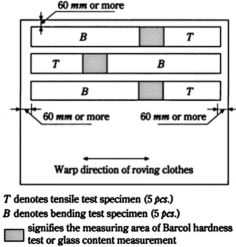
Fig 2.1 Location of Selection of Test Specimens
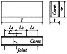
(2) When the cores are reckoned in strength, joints are to be provided at two locations.
![]()
30 Guidance relating to the Rules for the Classification of FRP Ships 2014
![]()
3. Shape and size of the test specimens
The shape and size of the test specimens are to be in accordance with Table 2.1.
ᾼNmm Ń | ᾎNmm Ń |
ᾼ≤20 | 30±0.5 |
20<ᾼ≤35 | 50±0.5 |
35<ᾼ≤50 | 80±0.5 |
Table 2.1 Shape and Size, etc. of Test Specimens
Item | Sandwich construction | Quantity |
Thickness of moulding | Bend test specimen, shearing test specimen and tensile test specimen are to be used. | - |
Barcol hardness | - | - |
Glass content | - | 3 |
Bend test specimen and shearing test specimen | Shearing test specimen
ᾼ = original thickness ÃÌ = 100 ~ 200 ÃĪ = 100 ᾨ = 2ÃÌ + ÃĪ + 60 Ǽ = approx. 10(mm ) (When the cores are reckoned in strength, a joint is to be provided at the position shown on the drawing.) | 5 |
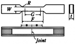
Tensile test specimen |
ᾼ = original thickness  = 60 ± 0.5 Ä = 50 ± 0.5 E = 25 or more Ĉ = 60 or more ㆍWhen the cores are reckoned in strength, a joint is to be provided at the centre of the parallel part. ㆍThe gripped portion is to be reinforced. | 5 |
![]()
Guidance relating to the Rules for the Classification of FRP Ships 2014 31
![]()
4. Test Procedures
(1) Thickness of moulding
The thickness of the shearing test specimens and tensile test specimens is to be measured.
(2) Tensile strength
(A) The test specimens are to be in accordance with Table 2.1.
(B) The tensile speed is to be 5 mmÕmi nǾ as the standard.
(C) When the test specimen fails at position outside the gauge length, the measured values of
the test specimen are not to be accepted and a new test specimen is to be additionally.
(D) The tensile strength is to be of the value obtained from the following formula.
Č NNÕmmĪ Ń
ÜĂ ᾏ
Aᾚ ÑAᾏÜĂᾚ
tested
where:
Č : Breaking load(kg)
Ī
Aᾏ : Sectional area of core(mm )
Ī
Aᾚ : Sectional area of FRP laminates(mm )
Ăᾏ : Modulus of tensile elasticity of core obtained by the test in Ch 3, 206.
Rules(NÕmmĪ )
Ăᾚ : Modulus of tensile elasticity of FRP laminates obtained by Ch 3, Sec
of the
28 of
Guidance for Approval of Manufacturing Process and Type Approval, etc.
(3) Shearing strength
The test procedure are to be in accordance with Ch 3, Sec 28 of Guidance for Approval of Manufacturing Process and Type Approval, etc. The side of FRP with a thicker layer is to be taken as the compression side.
5. Test Results
(1) Test results of sandwich constructions is to be recorded on the Table 2.2 and Table 2.3. ![]()
![]()
![]()
Table 2.2 Tensile Test Results of Laminates of Sandwich Constructions
Location of selection | Item | ||||||
Breadth of test specimen (mm ) | Thickness of test specimen (mm ) | Thickness of core (mm ) | Thickness of laminatesNÌŃ (mm ) | Braking load (C) | Tensile strength (CÕᾩᾩĪ) | RemarkNĮŃ | |
Mean value | (2) | ||||||
Notes (1) The thickness of laminates is to be obtained by deducting the thickness of the core from the total thickness of the sandwich constructions. (2) The mean value of tensile strength is to be obtained by taking the mean of the smaller three. (3) In "Remarks" column, the position of failure and existence of joint(s) are to be entered. | |||||||
![]()
32 Guidance relating to the Rules for the Classification of FRP Ships 2014
Location of selection | Item | |||||||||
Breadth of test specimen (mm ) | Thickness of test specimen (mm ) | Thickness of core (mm ) | Thickness of laminatesNÌŃ (mm ) | Č NĪŃ Ü₣ (C) | NĮŃ Ě (cmĮ ) | NĨŃ Ě (cmĮ ) | Breaking load (C) | Shearing strengthNJŃ (CÕᾩᾩĪ) | Remark NKŃ | |
Mean value | NĴŃ | |||||||||
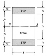
ÃÌ : (mm ) Notes (1) The thickness of laminates is to be obtained by deducting the thickness of the sandwich constructions. Č (2) Ü₣ is the gradient of straight portion of load-strain curve and the value of strain of either the outer layer or inner layer whichever is the greater is to be taken. ÃÌ N Č Ń Ň Į Į (3) Ěᾙ Ņ ÜĪĂ ᾚ Ü₣ × ÌL Ncm Ń ÃÌ : Outer span(mm ) Ăᾚ : Modulus of elasticity of FRP laminates which is of the value obtained from the test specified in 4. (1) (E) above.(kgÕmmĪ ) (4) Ěᾏ is the section modulus of the test specimen of sandwich constructions obtained by calculation. Ó Ì NᾼĮ Ñ ᾼĮ ŃÑ ᾼ ←Ī Ñ ᾼ ←Ī Ŏᾎ ÜÌĪ Ì Ī Ì Ì Ī Ī Ěᾏ Ņ ÜÌ ÜᾼĪ Ñ ←Ī Where : ᾼÌ , ᾼĪ (ᾼÌ Q ᾼĪ ), ᾼᾏ , ᾎ : As specified in the following Figure ← Ņ NᾼÌ Ñ ᾼĪ Ñ Īᾼᾏ ŃᾼĪ , ← Ņ NᾼÌ Ñ ᾼĪ Ñ Īᾼᾏ ŃᾼÌ Ì ÜĪNᾼ Ñ ᾼÌ Ń Ī Ī ÜĪNᾼ Ñ ᾼÌ Ń Ī (5) The shearing strength is of the value obtained from the test specified in 4. (3) above. (6) The mean value of shearing force is to be obtained from the mean of three in a smaller group. (7) In “Remarks” column, the position of failure and existence of joint(s) are to be entered. | ||||||||||
![]()
Table 2.3 Shearing Test Results of Laminates of Sandwich Constructions
![]()
![]()
ᾙ ᾏ
![]()
![]()
Guidance relating to the Rules for the Classification of FRP Ships 2014 33
![]()