Iranian Classification Society Rules

< Previous | Contents | Next >
Section 1 General
101. Application
1. In application to 101. 5 of the Rules, the terms "determined at the discretion of this Society" mean to comply with the requirements specified in the following 2. through 7.
2. Application
(1) This requirement is applied to the ships which are subject to Korean Ship Safety Act and Notification having a restricted to domestic service.
(2) For the items not mentioned in this requirements, they are to be comply with related require- ments on Korean Ship Safety Act.
3. Definition
(1) "Vehicle area" means the vehicle loading area indicated in vehicle arrangement.
(2) "Vehicle deck" means the deck providing passageway of vehicles or vehicle loading deck pro- viding in vehicle area.
(3) "Open space" means the followings:
(A) The bulkhead is not provided at the end of fore and after, and openings are not provided
on the shell plating of vehicle area. In this case, the area of openings on the upper deck of considering area is to be comply with the followings.
≥
= area of opening on the upper deck
= area of vehicle deck
(B) When the openings are provided on the both side shell plating in vehicle area, the area of opening is comply with the following.
≥
= as specified in (A)
= area of opening on one side in vehicle area.
= area of shell plating on one side in vehicle area.
(4) "Closed space" means closed space with weathertight other than above mentioned (3)
4. Submission of plans and documentations
For the securing device of vehicle and cargo, the following plans and documentations are to be submitted.
(A)Data which is able to be conformed the foreordinated route of ship, (for examples; conviction certificate of Owner or provisional Approvals for operation issued by the Authority).
(B) Vehicle and cargo loading plan
5. Vehicle area
(1) Either one of the following equipment is to be provided to the ships having a closed space.
(A) CCTV which is capable of monitoring the whole vehicle area on the navigation bridge
(B) Light indicator and audible alarm which is capable of confirming the state of ing/closing of vehicle area entrance door on the navigation bridge
(2) Indication in vehicle area
(A) In the vehicle area, the passageway for the using of access door, stairway, life saving
open-
appli-
Guidance Relating to the Rules for the Classification of High Speed and Light Crafts 2015 3
Pt 1 Ch 1
Classification and Surveys
![]()
Classification Pt 1, Ch 1
ances or fire extinguishing appliances is to be provided. This passageway is to be dis- criminated boundary line with easily visible color.
(B) For the ferries, when the lamp or inside door is not provided in location of fore peak bulk-
head the warning mark "Vehicles may not be loaded forward the fore peak bulkhead" is to be provided.
(C) Vehicle area is to be marked clearly and vehicle load plan including following items is to
be posted in the location where they are easily recognized.
(a) Maximum load of ship
(b) Maximum number of vehicles
(c) Notice items in loading vehicle
(D) "Notice items in loading vehicle" in (C) (c) is as follows and is to be included in vehicle and cargo load plan.
(a) Axle loads are not to exceed 00 ton(axle load is reviewed based on the maximum load 00 ton truck.
(b) The total weight of vehicles(including loaded on the vehicle) which is loaded on ship
are not to exceed 00 ton(the total weight of vehicles is reviewed based on the num- ber(00 vehicles) of maximum load 00 ton truck.)
(c)
When
proper
the loaded vehicles are increased according to the loading of similar vehicles,
type and number of movable securing devices which has sufficient strength is to
be provided additionally.
(d) When similar vehicles are loaded, the loading and arrangement of the vehicles are to be properly to ensure the stability.
6. Vehicle load method and securing device
(1) Vehicle load method
(A) Vehicles are to be loaded toward the direction of bow and stern. However, when the suffi- cient additional treatments for transverse sliding such as wedges etc. are provided, it may
not be needed.
(B) Vehicles are not to be loaded forward the fore peak bulkhead.
(C) The space between loaded vehicles is not to be less than 600 mm.
(D) In the vehicle area, boundary line with easily visible color or the protection is to be pro- vided for the access prohibition within 1 m near the access door, stairway and fire ex- tinguishing arrangements.
(E) Vehicles are to be arranged to allow sufficient space for the passageway leading to assem- bly stations and embarkation stations etc. in an emergency.
(2) Vehicle securing method
(A) Vehicles are to be secured to the ship by fixed securing devices(e.g.: D-ring, Clover socket and Deck eye plate etc.) and movable securing devices(e.g.: Web lashing, Turn buckle and Chain etc.) which are comply with the requirements in (4).
(B) Securing devices(fixed and movable securing devices) fixing vehicles and general cargos are to be approved by the Society. However, when securing devices are manufactured by ap- proved manufacturer which is approved by the Society according to international standard such as ISO etc., the approval may be replaced by the manufacturer's certificate.
(C) Sufficient number of fixed securing devices are to be provided to consider the loading of vehicles which are not marked in vehicle and cargo loading plan.
(D) movable securing devices for the ships(1,000 tons gross tonnage and above) engaged in coastal service and it's over are to be provided to more than 1.2 times of approved amount.
(E) The securing of vehicle is to be loaded in accordance with vehicle and cargo loading plan.
Before and during the voyage, it is to be checked by crews.
(F) The securing of vehicle is to be secured by more than 4 wheels or 2 parts of front and rear of vehicle using provided securing devices in vehicle and more than 4 fixed securing devices.
(G) For the ships which is only engaged in smooth water and having not more than 30 min. of
navigating time, the ships which has less than 1 hour of navigating time in smooth water and coastal area service and loaded with cars, less than 12-seater's passenger vans and 1.5 ton truck (For the ship having a port of call in middle of operation, a port of call as re- garded as departure port and arrival port), if they have a sufficient treatments for non-slip
as keys etc. with smooth sea condition(wave height is to be less than 1.5 m and wind
speed is to be less than 7 m sec), vehicles may not be secured.
4 Guidance Relating to the Rules for the Classification of High Speed and Light Crafts 2015
Pt 1 Ch 1
Classification and Surveys
![]()
Classification Pt 1, Ch 1
(3) Vehicle cargo loading
(A) The capacity of cargo being loaded on the vehicle is to comply with following requirements.
(a) The length of loaded cargo is to be less than the length of vehicle plus one tenth of the length of vehicle
(b)
(c)
The width of loaded cargo is to be less than the range which can be checked by rear view mirror.
The height of loaded cargo is to be less than 4 m from the ground. Where the truck such as a van etc. having cargo space with roof cover, the height is from the ground to the top of the cover.
(B) Cargo being loaded on the vehicle is to be secured to ensure the load by the movements of ship which is described in the (4).
(4) Strength of securing device
(A) The definitions of terms that are used to assess the strength of the securing devices are as follows.
= total weight of vehicle(load + vehicle weight) (ton )
= longitudinal, transverse and vertical distance from the center of rolling and pitch-
ing to the center of under consideration vehicle, respectively
= rolling and pitching angle of ship as specified in Table 1 respectively (deg) (see
Fig. 1)
= force acting to transverse direction which is parallel to deck during rolling of ship (ton) (see Fig. 1)
= force acting to longitudinal direction which is parallel to deck during pitching of
ship (ton) (see Fig. 1)
= overturing moments during rolling of ship (ton-m) (see Fig. 2)
= forces acting on vehicle which is parallel to longitudinal and transverse deck re- spectively (ton)
= full width of vehicle (m) (see Fig. 2)
= spacing of wheels (m) (see Fig. 2)
= height from deck to the center of gravity of the vehicle (m) (see Fig. 2)
= sum of the transverse and longitudinal horizontal component which movable secur-
(B) The
= sum of the force to resist for vehicle overturning moment by movable securing de-
vices (ton)
= number of movable securing devices used for one vehicle
= transverse and longitudinal angle between movable securing devices and deck re- spectively (deg) (see Fig. 2)
= height from deck to the point of vehicle securing (m) (see Fig. 2)
= safety working load of movable securing devices which is divided breaking load with safety factor of Table 1 (ton)
= friction coefficients between vehicle and deck, as shown below
tire(rubber) / non-slipped paint: 0.7 tire(rubber) / steel deck: 0.3
steel / steel deck: 0.1(when dry)
steel / steel deck: 0.0(when wet) timber / steel deck: 0.3
loads acting on the securing device is to be determined in consideration of the move-
ments of ship which is described in the Table 1.
Guidance Relating to the Rules for the Classification of High Speed and Light Crafts 2015 5
Pt 1 Ch 1
Classification and Surveys
![]()
Classification Pt 1, Ch 1
Table 1 Ship motion
Rolling | Pitching | Safety factor | ||
degree | cycle 3) | degree | cycle | |
10° | cycle of ship | 5° | 5 sec | 4 over |
(Note) 1. ′ is the value obtained from the following formula. ′ = the vertical position of the centric of the ship = the vertical position of the buoyancy centric of the ship 2. The centric of pitching is to be longitudinal position of the centric of the ship. 3. The rolling cycle of the ship may be taken from of Pt 3, Ch 2, 203. 2. of the Rule. | ||||
(C) Each component of the
2.
loads caused by motions of the ship is shown in Fig. 1 and
Table
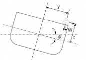
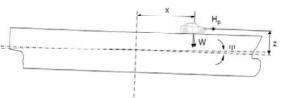
Fig. 1 Motions of the ship
Table 2 Load components
Type | Load components (ton ) | |||
Vertical force | Horizontal force | |||
transverse | longitudinal | |||
Static load | Rolling | cos |
| - |
Pitching | cos | - |
| |
Combination | cos cos |
|
| |
Dynamic load | Rolling |
|
| - |
Pitching |
| - |
| |
6 Guidance Relating to the Rules for the Classification of High Speed and Light Crafts 2015
Pt 1 Ch 1
Classification and Surveys
Classification Pt 1, Ch 1
![]()
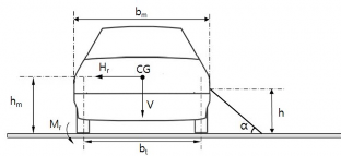
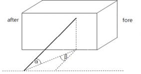
Fig. 2 Various dimensions during vehicle securing
(D) The forces caused by motions of the ship are as follows.
(a) Vertical force: the smallest among and
cos cos
cos
cos
(b) Transverse horizontal force:
sin
(c) Longitudinal horizontal force:
sin
(E) The loads to be considered as acting lowing formula.
(a) Transverse horizontal force
on the vehicle are to be determined according to fol-
(b) Longitudinal horizontal force
Guidance Relating to the Rules for the Classification of High Speed and Light Crafts 2015 7
Pt 1 Ch 1
Classification and Surveys
![]()
Classification Pt 1, Ch 1
(c) Rolling overturing moments
× ×
(F) The forces caused by motions of the ship are as follows.
(a) Transverse horizontal component:
· cos ·cos
(b) Longitudinal horizontal component:
· cos ·sin
(c) overturing moments horizontal component:
· sin
(G) Movable securing devices are to be complied with following formula.
(a) Transverse horizontal component : ≤
(b) Longitudinal horizontal component : ≤
(c) overturing moments horizontal component : ≤
(5) Drawing guidance for vehicle and cargo loading plan
(A) The arrangement and loading method of vehicles intended to load among the vehicles as specified in "Enforcement Regulations of the Automobile Management Act Appendix Table 1" is to be indicated in the loading plan. In this case, where the total weight of the vehicle is within the range of the total weight of the approved vehicle and fixation method and se- curing strength is suitable, other vehicles, construction machinery as specified in "Presidential Decree for the Construction Machinery Management Act Appendix Table 1" and agricultural machinery as specified in "Enforcement Regulations of the Agricultural Mechanization Promotion Act Appendix Table 1" etc. are to be loaded in accordance with the loading plan.
(B) Notwithstanding the (A) above, where the vehicle type intended to load is decided by the owner of ship especially, the vehicle loading plan reflected the arrangement and loading method of the vehicle is to be approved.
(C) Where intended to load the vehicle other than (A) above, the vehicle loading plan reflected the arrangement and loading method of the vehicle is to be approved additionally. .
(D) Vehicle and cargo loading plan is to be included following items.
(a) arrangement and detail of fixed securing devices(types, material, breaking strength etc.)
(b) detail of movable securing devices(material, breaking strength, instructions etc.)
(c)
arrangement and securing details for the vehicles intended to load(position of securing point of vehicle and ship, type of movable securing devices)
(d) specification of the vehicles intended to load(length and width of vehicle, vehicle weight
including cargo weight)
(e) fire-extinguishing appliances, drainage facilities and passageway
(f) notice in Par 6 (8) (D)
(g) when cargoes other than vehicles are loaded, the description of loading and securing method
(E) The plan is to be not less than a 1:200 scale.
(6) Cargo loading other than vehicles
(A) In the vehicle area, unless it is approved by the Society, no cargoes other than vehicles may be loaded. For the cargoes loading other than vehicles, the documents for the closure and loading arrangements by the kinds of cargoes are to be submitted and approved by this Society.
(B) For freight container in one tier, the container is to be secured at their lower 4 corners by fixed securing devices(socket, D-ring, sliding base, lashing plate etc.) which is secured to
the ship. For freight container in more than two tiers, the container is to be
secured at
their lower 4 corners to the upper 4 corners of below container by movable securing de-
8 Guidance Relating to the Rules for the Classification of High Speed and Light Crafts 2015
Pt 1 Classification and Surveys
Ch 1 Classification Pt 1, Ch 1
![]()
vices(twist lock, stacker etc.) or the container is to be secured directly to ship by lashing rod or turnbuckle. These fixed and movable securing devices are to comply with the re- quirement in Guidance Pt 7, Annex 7-2.
(C)
hGiecnle randcacragrogeos(elxocalduidnigngplapnassiet'nsgearrsanpgeermsoennatl · bleoloadnignigngs·) secxucreipntg cmaregtoheosd aipsprtovebde
ilnoadved-
in storage facilities to made available for securing and is to be secured to comply with the requirement in (4).
7. Electric equipment
(1) Installation and utilization of electricity supply cables to loaded vehicle
(A) A ship with enclosed vehicle loading space which carries live-fish transporting trucks must be installed with reel lead electricity supply cables which satisfies the below requirements, readily available to supply electricity for every each vehicle it carries.
(a) Must have a circuit breaker for overload
(b) Cables must be fire resistant
(B) A live-fish transporting truck on board the ship must have it's engine turned off during the voyage and acquire the electricity necessary for oxygen supplier from the ship. ![]()