Iranian Classification Society Rules

< Previous | Contents | Next >
Annex 3-2 Guidance for Buckling Strength Calculation
1. Buckling Strength Calculation for Steel Ships
(1) General
(A) Symbols used are as follows.
: thickness of plating (mm )
: shortest side of plate panel (m )
: longest side of plate panel (m ) (= length in m of stiffener, pillar, etc.)
: modulus of elasticity of the material (= 2.06․105 N mm for steel)
the ideal elastic (Euler) compressive buckling stress (N mm
: minimum upper yield stress of material (N mm ), may be taken as 235
for normal strength steel. For higher strength steel, the requirements specified in
Pt 3, Ch 3, 501. are to be applied.
: the ideal elastic(Euler) shear buckling stress (N mm
minimum shear yield stress of material (= ) (N mm
:
the critical compressive buckling stress (N mm
)
: the critical shear stress (N mm )
calculated actual compressive stress (N mm
:
) calculated actual shear stress (N mm )
vertical distance (m ) from the baseline or deckline to the neutral axis of the hull girder, whichever is relevant
vertical distance (m ) from the baseline or deckline to the point in question below or above the neutral axis, respectively.
(B) Relationships for buckling strength calculation are as follow.
(a) when
:
= when
:
=
=
(b) when : =
when :
(c) when the required
,
known, the
or
will from the above ex-
pressions of Johnson-Ostenfeld relationship be:
= and
: from Fig 3.1 or from the formula as follow.
=
For = 1
Guidance Relating to the Rules for the Classification of High Speed and Light Crafts 2015 21
![]()
(2) Longitudinal Buckling Load
For longitudinal stresses, the requirements specified in Pt 3, Ch 2, 401. are to be applied.
(3) Transverse Buckling Load
Transverse hull stresses in compression may occur from:
(A) transverse loads and moments in twin hull craft, the requirements specified in Pt 3, Ch 2,
402. are to be applied.
(B) supports of craft's side structure, the requirements specified in Pt 3, Ch 3, Sec 5 and Sec 6 are to be applied.
(4) Plating
(A) Plate panel in uni-axial compression
(a) The ideal elastic buckling stress may be taken as:
N mm
: coefficient in accordance with Table 3.6
= 1.21 (when stiffeners are angles or T-sections)
= 1.10 (when stiffeners are bulb flats)
= 1.05 (when stiffeners are flat bars)
For double bottom panels the -values may be multiplied by 1.1
: the ratio between the smaller and the larger compression stress assuming linear variation in accordance with Table 3.2
(b) The critical buckling stress is to be related to the actual compression stresses as follows.
: calculated compression stress in plate panels. With linearly varying stress
across the plate panel, is to be taken as the largest stress
= 1.0 : for deck, side, single bottom and longitudinal bulkhead plating
= 0.9 : for bottom and inner bottom plating in double bottoms
=
: for locally loaded plate panels where a normal load level is
applied
and : static and dynamic parts
(c) The resulting thickness requirements, before elastic buckling, will be as follows.
- with stiffeners in direction of compression stress :
mm
- with stiffeners perpendicular to compression stress :
mm
22 Guidance Relating to the Rules for the Classification of High Speed and Light Crafts 2015
![]()
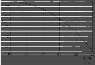
Fig 3.1 Factor Fig 3.2 Buckling Stress Correction Factor
(B) Plate panel in shear
(a) The ideal elastic buckling stress may be taken as follows.
N mm kt s
(b) The critical shear stress is to be related to the actual shear stresses as follows.
≥
= 0.9 : for craft's sides and longitudinal bulkheads subjected to hull girder shear forces
= 0.95 : for local panels in girder webs when nominal shear stresses are cal- culated ( )
= : for local panels in girder webs when shear stresses are determined by fi- nite element calculations or similar
(c) The resulting thickness requirement will be as follows.
mm
(C) Plate panel in bi-axial compression and shear
(a) For plate panels subject to bi-axial compression and in addition to in-plane shear stress- es the interaction is given as follows.
≤
compression stress in longitudinal direction (perpendicular to stiffener spacing )
: compression stress in transverse direction (perpendicular to the longer side
: critical buckling stress in longitudinal direction (perpendicular to stiffener
Guidance Relating to the Rules for the Classification of High Speed and Light Crafts 2015 23
![]()
ing )
: critical buckling stress in transverse direction (perpendicular to the longer
side
of the plate panel)
= 1.0 : for plate panels where the longitudinal stress or other
stress is incorporated in and constitutes a major part of
= 0.95 in other cases
or
: factors given in Table
,
: as specified in (B) (b)
(b) Shear stresses are to be considered in combination
with the follows cases.
- uni-axial compression may be written : or ≤ or
- bi-axial compression : ≤
- for bi-axial compression alone : =
Table 3.6 Factor (
structure | Factor ( ) |
plating with longitudinal stiffeners (in the direction of compression stress) | ≤ ≤
|
plating with transverse stiffeners (perpendicular to the compression stress) |
≤ ≤
|
Table 3.7 Factors , and
|
|
| |
1.0 〈 ≤ 1.5 | 0.78 | -0.12 | 1.0 |
1.5 〈 〈 8 | 0.80 | 0.04 | 1.2 |
(5) Stiffeners in Direction of Compression
(A) Lateral buckling mode
(a) The ideal elastic lateral buckling stress may be taken as follow.
A
N mm i
: moment of inertia about the axis perpendicular to the expected direction ling (cm )
: cross-sectional area (cm )
(b) The formula for the critical buckling stress is as follows.
of buck-
24 Guidance Relating to the Rules for the Classification of High Speed and Light Crafts 2015
![]()
- When calculating and , a plate flange equal to 0.8 times the spacing is included for stiffeners.
- The critical buckling stress is to be in accordance with requirements specified in (1)
(B).
- The formula for the ideal elastic lateral buckling stress is based on hinged ends and axial force, only.
- Continuous stiffeners supported by equally spaced girders are regarded as having hinged ends when considered for buckling.
- In case of eccentric force, additional end moments or additional lateral pressure, the
strength member is to be reinforced to withstand bending stresses.
(c) For longitudinal structures, the critical buckling stress is the same as (A) (a) above and the actual compression stress is to be satisfied with the follows.
: actual compression stress(N mm ), for the local load stress, the value of stress
divided by specified in (4) (A) (b) above.
= 0.85 : for continuous stiffeners
simultaneous bending moment at midspan

=
bending moment capacity
(d) The resulting maximum allowable slenderness is to as follows.
(B) Torsional buckling mode
(a) For longitudinal structures, the ideal elastic buckling stress for the torsional mode is to be in accordance with the separate requirements deemed appropriate by the Society.
(b) The critical buckling stress is to be satisfied by the following conditions.
≥
: actual compression stress(N mm
), for the local load stress, the value of
(c)
stress
divided by specified in (4) (A) (b) above.
= 0.8 : when the adjacent plating is allowed to buckle in the elastic mode, ac- cording to the requirements specified in (7).
= 0.85 : in general
To avoid torsional buckling, the dimension is to be decided according to the kind of stiffener.
mm
: thickness of web (mm
Guidance Relating to the Rules for the Classification of High Speed and Light Crafts 2015 25
![]()
- Flanged profiles are to be satisfied by the following conditions.
- Minimum flange breath should not to be less than the follows.
mm (for symmetrical flanges)
mm (for unsymmetrical flanges)
(C) Web and flange buckling
(a) The buckling stress required for the web is to be as follows.
N mm
and : web thickness and height (mm )
(b) The ideal elastic buckling stress of flange of stiffeners is to be as follows.
N mm
: flange thickness (mm )
: flange width for angles, half the flange width for T-sections
(c) The flange thickness is to be in accordance (c).
(d) The flange width is to be as follows.
with the requirements specified in (4) (A)
mm
(6) Stiffeners Perpendicular to Direction of Compression For longitudinal structures, the moment of inertia of the follows.
the stiffener section is not to be less than
cm
: span of stiffener (m )
: spacing of stiffener (m )
: plate thickness (mm )
,
: actual compression stress(N m m
), for the local load stress, the value of stress
26 Guidance Relating to the Rules for the Classification of High Speed and Light Crafts 2015
![]()
by specified in (4) (A) (b) above.
(7) Elastic Buckling of Stiffened Panels
(A) Elastic buckling as a design basis
(a) Elastic buckling may be accepted for plating between stiffeners when ;
i.e.
- (stiffener in direction of compression) >
(plating in
pression)
: according to (5) and (1) (B). To be multiplied by
direction of com- for ordinary local
load.
N mm
(B) Allowable compression
(a) The allowable compression force in the panel may be increased form to
KN
kN
and = : according to (4) (A) and (5). to be multiplied by for ordi-
and : according to (4) (A) and (5). Ordinary effective flange is to be used
for stiffeners
= : fraction of participating in the post-buckling stress increase
: ultimate average
(b) For transversely stiffened plating, the ultimate average stress of plating is as follows.
(kN)
(c) may be substituted for ance with (4) (C).
when calculating bi-axial compression and shear in accord-
Guidance Relating to the Rules for the Classification of High Speed and Light Crafts 2015 27
![]()
(8) Girders
(A) Girders perpendicular to direction of compression
(a) When the compression stresses are applied on girders which support stiffeners, the mo- ment of inertia of the girder section is not to be less than the follows.
(cm )
: span of girder (m )
: distance between girder (m )
: spacing of stiffener (m )
: moment of inertia of stiffener (cm
: according to (5) (A)
: according to (1) (B)
(B) Buckling of effective flange
(a) Plating acting as effective flange for girders which have a satisfactory buckling strength.
support crossing stiffeners should
(b) Compression stress arising in the plating due to local loading of girders are to be less
than × critical buckling strength specified in (1) (B) and (4) (A). When calculating the compression stress, the effective flange is to be the distance between girders.
2. Buckling Strength Calculation for Aluminium Alloy
(1) General
(A) Symbols
: thickness of plating (mm )
: shortest side of plate panel (m )
: longest side of plate panel (m )
: modulus of elasticity of the material for aluminium (=0.69×10⁵
: the ideal elastic (Euler) compressive buckling stress (N mm
: )
usually base material properties are used, but critical or extensive zones may have to
be taken into account.
: the ideal elastic (Euler) shear buckling stress (N m m
: minimum shear yield stress of material ( )
:
: the critical shear stress (N mm
o : calculated actual
: calculated actual
compressive stress (N mm
shear stress (N mm
: vertical distance from the baseline or deckline to the neutral axis of the hull girder, whichever is relevant (m )
: vertical distance
from the baseline or deckline to the point in question below
or above the neutral axis, respectively (m )
28 Guidance Relating to the Rules for the Classification of High Speed and Light Crafts 2015
![]()
(B) Relationships
(b) when
, when
,
,
(c) When the required or is known, the necessary or will from the above ex- pression of the Johnson-Ostenfeld relationship be
and
: from Fig 3.1 or from formula
or
:
For
(2) Longitudinal buckling load
See Pt 3, Ch 2, 401. of the Rules.
(3) Transverse buckling load
Transverse hull stresses in compression may occur from:
(A) transverse loads and moments in twin hull craft, see Pt 3, Ch 2, 402. of the
(B) supports of craft’s side structure, see Pt 3, Ch 4, Sec 7 of the Rules.
(4) Plating
(A) Plate panel in uni-axial compression
(a) The ideal elastic buckling stress may be taken as:
Rules.
N mm
: see Table 3.6
= 2.50 (when stiffeners are hollow profile with <0,5 and the enclosed area of the hollow profile is larger than 20 st)
= 1.21 (when stiffeners are angles or T-sections)
= 1.10 (when stiffeners are bulb flats)
= 1.05 (when stiffeners are flat bars)
For double bottom panels the c-values may be multiplied by 1.1.
is the ratio between the smaller and the larger compressive stress assuming linear variation, see Fig 3.2.
(b) The critical buckling stress is to be related to the actual compressive stresses as fol- lows:
: calculated compressive stress in plate panels. With linearly varying stress across
= 1.0 : for deck, side, single bottom and longitudinal bulkhead plating
= 0.9 : for bottom and inner bottom plating in double bottoms
Guidance Relating to the Rules for the Classification of High Speed and Light Crafts 2015 29
![]()
= 1.0 : for locally loaded plate panels where an extreme load level is applied
=
: for locally loaded plate panels where a normal load level is
applied (e.g. plating acting as effective flange for girders)
and : static and dynamic parts of .
(c) The resulting thickness requirement (before elastic buckling) will be:
- with stiffeners in direction of compressive stress :
mm
- with stiffeners perpendicular to compressive stress :
(B) Plate panel in shear
(a) The ideal elastic buckling stress may be taken as:
N mm Kt
s
(b) The critical shear stress is to be related to the actual shear stresses as follows:
= 0.9 : for craft’s side and longitudinal bulkhead subject to hull girder shear
= 0.95 : for local panels in girder webs when nominal shear stresses are lated
= : for local panels in girder webs when shear stresses are determined by finite
element calculations or similar
(c) The resulting thick1ness requirement will be:
mm
(C) Plate panel in bi-axial compression and shear
(a) For plate panels subject to bi-axial compression the interaction between the longitudinal and transverse buckling strength ratios is given by:
≤
: compressive stiffness in longitudinal direction (perpendicular to stiffener spacing s)
: compressive stress in transverse direction (perpendicular to the longer side
of the plate panel)
: critical buckling stress in longitudinal direction (perpendicular to stiffener spacing s)
: critical buckling stress in transverse direction (perpendicular to the longer side
30 Guidance Relating to the Rules for the Classification of High Speed and Light Crafts 2015
![]()
: for plate panels where the longitudinal stress or other stress
is incorporated and constitutes a major part in
: other cases
or
: see Table
: as given (B)
(b) For shear in combination with:
- uni-axial compression : or ≤ or
- bi-axial compression, approximately :
≤
- for bi-axial compression alone = 1
(5) Stiffeners in Direction of Compression
(a) The ideal elastic lateral buck1ing stress may be taken as:
N mm
: moment of inertia about the axis perpendicular to the expected direction of ling (cm )
: cross-sectional area (cm )
(b) Critical buckling stress is as follows:
buck-
- When calculating and , a plate range breadth equal to 0.8 times the spacing is included for stiffeners.
- The critical buckling stress is found from (1) (B).
- The formula given for
is based on hinged ends and axial force only.
(c)
- Continuous stiffeners supported by equally spaced girders are regarded as having hinged ends when considered for buckling.
- In case of eccentric force, additional end moments or additional lateral pressure, the strength member is to be reinforced to withstand bending stresses.
For longitudinals and other stiffeners in the direction of compressive stresses, the critical buckling stress calculated in (A) is to be related to the actual compressive stress as fol-
lows:
≥
: calculated extreme compressive stress, or ordinary local load stress divided by
,
4. (A) (b)
Guidance Relating to the Rules for the Classification of High Speed and Light Crafts 2015 31
![]()
= 1 - : maximum 0.85 for single-span stiffeners

=
bending moment capacity
(d) The resulting maximum allowable slenderness will be:
(B) Torsional buckling mode
(a) For longitudinals and other stiffeners in the direction of compressive stresses, the ideal elastic buckling stress for the torsional mode may in general be followed the appropriate requirements of the Rules.
(b) The critical buckling stress is not to be less than:
≥
: calculated extreme compressive stress, or ordinary local load stress divided by
,
4. (A) (b)
= 0.8 : when the adjacent plating is allowed to buckle in the elastic mode, accord- ing to (7)
(c) To avoid torsional buckling the following scantling is to
- the height of flats should not exceed:
keep:
mm
: thickness of web (mm
)
- Minimum flange breadth may be taken as:
mm (For symmetrical
mm (For unsymmetrical
(C) Web and flange buckling
(a) The
value required for the web buckling mode may be taken as:
mm
32 Guidance Relating to the Rules for the Classification of High Speed and Light Crafts 2015
![]()
and : web thickness and height (mm )
(b) The ideal elastic buckling stress of flange of angle and tee stiffeners may be calculated from the following formula:
N mm
(c)
: flange thickness (mm )
: flange width for angles, half the flange width for T-sections
Web thickness, see plating with stiffener in direction of compression stress, (4) (A) (c).
(d) Flange width from web:
(6) Stiffeners perpendicular to direction of compression
For stiffeners supporting plating subject to compression stresses perpendicular to the stiffener di-
rection the moment of be less than:
inertia of the stiffener section (including effective plate flange) is not to
cm
: span of stiffener (m )
: spacing of stiffener (m
)
: calculated extreme compressive stress, or ordinary local load stress divided by
: Fig 3.1
(7) Elastic buckling of stiffened panels
(A) Elastic buckling as a design basis
(a) Elastic buckling may be accepted for plating between stiffeners when:
-
- (of stiffener in direction of compression) > (of plating in direction of com-
pression)
: from (5) and (1) (B). To be multiplied by for ordinary local load.
(b) For the torsional buckling mode of flats may be taken:
Guidance Relating to the Rules for the Classification of High Speed and Light Crafts 2015 33
![]()
N mm
(B) Allowable compression
(a) The allowable compressive force in the panel may be increased from to
and : for plating and stiffener from (4)의 (A) and (5). to be by for ordinary local load.
and
and
for plating and stiffener, respectively, from (4)의 (A)
effective flange is to be used for stiffeners area of plating and stiffener (cm )
and (D). Ordinary
: fraction of participating in the post-buckling stress increase
: ultimate average
(b) For transversely stiffened plating (compressive stress perpendicular to longest side
of plate panel) is
= 0
kN
(c)
(8) Girders
may be substituted
when calculating uniaxial compression and shear (4) (C)
(A) Girders perpendicular to direction of compression
(a) For transverse girders supporting longitudinals or stiffeners subject to axial compression stresses, the ideal elastic buckling stress may be taken as:
N mm
: span of girder (m )
: distance between girders (m )
: spacing of stiffeners (m )
34 Guidance Relating to the Rules for the Classification of High Speed and Light Crafts 2015
![]()
(b) The
: moment of inertia of stiffener (cm )
: moment of inertia of transverse girder (cm )
: equivalent plate thickness of stiffener area (mm ) (= stiffener area / stiffener spac- ing)
critical buckling stress is not to be less than:
: calculated compressive stress (N m m
= 0.75
(B) Buckling of effective flange
(i) Plating acting as effective flange for girders which support crossing stiffeners is to have a satisfactory buckling strength.
(ii) Compressive stresses arising in the plating due to local loading of girders are to be less
than " x the critical buckling strength". When calculating the compressive stress
section modulus of the girder may be based on a plate range breadth equal
tance between girders.
![]()
(iii) Elastic buckling of deck plating may be accepted after special consideration.
to the dis-
![]()