Iranian Classification Society Rules

< Previous | Contents | Next >
Section 2 Welding of Aluminium Alloys
201. Groove design
1. The groove design of welded connections, as a rule, is to be in accordance with Table 2.2.1.
Grooves and root gaps which differ from these may be subject to special consideration.
2. To minimize distortion, the X groove with the narrowest root gap practicable is recommended for thick material, instead of single-V groove.
![]()
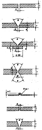
Table 2.2.1 Groove Design of TIG and MIG Welding
Groove design | Dimension | Remarks | |||
MIG |
| = | 1.5 ~ 5 | Welding from one side. | |
| = | 0 ~ 2 | Backing may be used. | ||
| = 5 ~ 25 = 0 ~ 3 = 1.5 ~ 3 = 60 ~ 100° | Largest angle is recommended for under-up position. Back chipping and rewelding should be carried out. | |||
| = 8 ~ 25 = 3 ~ 7 = 2 ~ 4 = 40 ~ 60° | Smallest joint angle may be used up to 15 mm and with the largest root gap. Position vertical, under-up and side-in require large root gap. | |||
| = 12 ~ 25 | Allowed specially for automatic welding. | |||
| = 0 ~ 2 | Semiautomatic processes may be used in all posi- | |||
| = 3 ~ 5 | tions, and shall be back chipped before welding | |||
| = 50 ~ 70° | from backside. | |||
TIG |
| ≤ | 2 | ||
| ≤ 4 = 0 ~ 2 | Welding from one side. | |||
| = 4 ~ 10 | Backing may be used in horizontal position | |||
| = 0 ~ 2 | ||||
| = 60 ~ 70° | ||||
= material thickness (mm ) = root face (mm ) = root gap (mm ) = joint angle | |||||
202. Welding procedure qualification test
Welding procedures used for welding of aluminium alloys are to have been approved by Society in
accordance with the requirements in
Ships.
Pt 2, Ch 2, Sec 4 of Rules for the Classification of Steel
203. Welders
Welders who engage in welding of aluminium alloys are to have been qualified by Society in ac- cordance with the requirements in Pt 2, Ch 2, Sec 5 of Rules for the Classification of Steel Ships.
204. Welding consumables
![]()
Welding consumables used for aluminium alloys is to be applied in accordance with Table 2.2.2.
![]()
Table 2.2.2 Application of Welding Consumables used for Aluminium Alloy
Kind and grade of aluminium alloys to be welded | Grade of applicable welding consumables | |
5000 series | 5754 P | RAlRA, RAlRB, RAlRC RAlW A, RAlW B, RAlW C |
5086 P, 5086 S | RAlRB, RAlRC RAlW B, RAlW C | |
5083 P, 5083 S | RAlRC, RAlW C | |
6000 series | 6005 AS | RAlRD , RAlW D |
6061 P, 6061 S | RAlRD , RAlW D | |
6082 S | RAlRD , RAlW D | |
(NOTES) (1) The symbols used for the materials in this table are same as the symbols specified in Ch 2, Pt 2, 608. of Rules for the Classification of steel ships. (2) For welded joint of 5000 series alloys and 6000 series, the welding consumables corresponding to 5000 series alloys specified in this table may be used. (3) For welded joint of 6000 series alloys, RAlR A /RAlW A, RAlRB/RAlW B or RAlR C/RAlW C in lieu of RAlR D/RAlW D may be used. | ||
205. Preparation for welding
1. Edge preparation
(1) Proper edge preparation is to be employed.
(2) Joint edge may be prepared by mechanical cutting, such as band sawing, arc cutting.
2. Cleanliness
and by plasma (TIG)
(1) All oil or other hydrocarbons, paint and loose particles from the sawed edges must be removed prior to welding.
(2) Oil or grease films may be removed chemically by dipping, spraying or wiping the aluminium
plate with solvents. Mildly alkaline solutions may be used for cleaning and all welding surfaces shall be thoroughly dried before welding.
(3) Oxide films, which will prevent fusion between the filler metal and the parent material are to
be removed from the weld bevels and a minimum of 75 mm to any side, prior to assembly.
Mechanical means, such as a
power-driven clean, stainless steel brush, or suitable chemical
means are to be used. Welding is to take place immediately after cleaning, and the welding site
is to be protected against draft,
3. Backing
wind and moisture.
(1) When backing is used, the joint angle is to be large enough to provide accessibility for the root runs.
(2) Besides aluminium alloys, stainless steel and copper may be used as backing bar material.
(3) When copper backing is used, copper pickup is to be prevented because local deposition can re- sult in corrosion service.
(4) Temporary aluminium backing is to be removed by chipping after welding. If the butt weld is not completely fused to the temporary aluminium backing, the root pass is to be back chipped
to sound metal after the backing bar has been removed. To ensure adequate penetration, the
temporary backing should be grooved.
![]()
(5) When permanent aluminium backing is used, it is necessary to obtain complete fusion between the backing, the root faces and the root layer of the weld. Permanent backing is not recom- mended where crevice corrosion is of a concern. In these conditions, all edges of the backing bars are to be completely welded.
![]()
206. Main welding
1. The welding process may be manual, semi-automatic or automatic according to welding procedure specifications.
2. TIG-welding is a recommended process for welding of thinner gages and precision weldments.
MIG-welding is recommended for thicker gages.
3. For MIG fillet welds, back stepping is recommended to fully fill the end crater and thereby elimi- nate cracking problems that usually accompany the crater.
4. Other welding methods such as resistance, spot, seam, stud or electron beam welding may be ap- proved by the Society after consideration in each separate case.
207. Preheating
1. Preheating of parts to be welded is to be carried out when the temperature of the parts is below 5
℃ or when the mass of the parts is such that the heat is conducted away from the joint faster
than the welding process can supply it. Use of preheat is required when welding is performed un-
der high humidity conditions.
2. The preheating temperature must be limited to maximum 60 ℃, due to the increased of stress corrosion cracking for Al-Mn alloys above this temperature.
susceptibility
208. Repair welding
1. Defects in the weld metal or adjacent base material, or both, are to be corrected by
complete re-
moval of the defect by chipping or grinding, followed by rewelding according to, in advance, ap- proved welding repair specification.
2. The same filler metal and welding process that was used in the original joint should be employed where possible.
209. Quality and inspection of welds
1. Penetrant examination
(1) The surface to be examined with a penetrant is to be clean and free from weld spatter and kept at room temperature at the time of examination. When temperatures range outside of 15 ℃
to 30 ℃, the examination technique at the proposed temperature requires qualification.
(2) Both colour (red) contrast penetrants and fluorescent penetrants may be used. Optimum penetrat- ing and developing time is required for each process to ensure that every defect will be revealed.
(3) Sufficient illumination is required to ensure adequate sensitivity during the examination and eval- uation of indicators. For red penetrants, good worklight is sufficient, and for fluorescent pene-
trants the examination is conducted in a darked area using filtered ultraviolet light (black light).
2. Radiographic examination
(1) The radiography of aluminium welds is normally to be carried out with a conventional x-ray tube. Gamma rays, as emitted from isotopes, should not be used for the radiography of alumi- nium, except for very heavy sections.
(2) Radiographic film should be of a medium to fine grain type.
(3) Al-wire type penetrameters are to be used. The sensitivity level shall be at least 2 %.
(4) The operator evaluating the film must have a documented minimum of 60 hours training and 12 months practical experience in radiographic testing.
3. Ultrasonic examination
(1) Ultrasonic examination procedures and related matters are left to the discretion of the Society.
(2) Ultrasonic examination has to be carried out with a higher amplification for aluminium welds because of the danger of lack of fusion.
(3) Because the sound velocity for aluminium and steel vary slightly, angle probes with small cor-
rections may be used for the sound angle as indicated in Table 2.2.3.
(4) The operator is to be certified in accordance with a recognized certification scheme accepted by
![]()
the Society.
Table 2.2.3 Angle of Probes
Steel | Aluminium |
35 | 33 |
45 | 42.4 |
60 | 55.5 |
70 | 63.4 |
210. Acceptance criteria fabrication
1. Visual inspection
(1) All welds are to show good workmanship with smooth transition to the base material sharp edges. An overlap or deficient weld is not acceptable.
(2) For butt welds, weld reinforcement or excessive penetration is not to exceed 2 mm .
(3) For fillet and partial penetration welds, weld reinforcement is not to exceed 3 mm .
(4) For throat thickness, a negative deviation from that which is specified is not allowed.
(5) The difference in leg lengths of a fillet weld is not to exceed 3 mm .
2. Non-destructive examination
![]()
Cracks, incomplete penetration and lack of fusion are not acceptable.
without