Iranian Classification Society Rules

< Previous | Contents | Next >
Section 1 General
101. Application
1. Hull structures, constructed in materials complying with the requirements in Sec 2, are to be com- ply with requirements in this chapter.
2. Requirements, not included in this chapter, are to be in accordance with those in Rules for the Classification of Steel Ships.
102. The scantling reduction
Scantling reductions for high speed and light craft structures, when compared with ordinary steel ship rules, are based on the following :
(1) Thorough corrosion protection of steel
(2) A stiffener spacing reduction ratio ( )
m , deep tank
m , other
(3) Longitudinal framing in bottom and strength deck
(4) Extended longitudinal and local buckling control
(5) Sea and weather service restriction
103. Bottom, side and deck structures
This chapter applies to single skin structures. Based on the changes in total stress pattern, it may also apply to double bottom and other cofferdam type structure adjustments.
104. Flat cross structure
1. A flat cross structure is a horizontal structure above the waterline, such as the bridge connecting structure between twinhulls.
2. A flat cross structure is normally to be longitudinally stiffened.
3. The stiffening of the central part of the upper deck is to result in achiving necessary transverse buckling strength.
105. Bulkhead structures
1. Transverse bulkheads
(1) The number and location of transverse watertight bulkheads is to be in accordance with the re- quirements given in Ch 1, 402.
(2) The stiffening of the upper part of a plane transverse bulkhead is to be such that the necessary
transverse buckling strength is achieved.
2. Corrugated bulkheads
(1) The spacing of corrugated bulkheads is defined according to Fig 3.3.1.
![]()
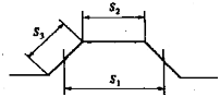
Fig 3.3.1 Corrugated Bulkheads
, spacing for section modulus calculation
or , spacing for plate thickness calculations in general
(2) Section modulus and thickness formulas for corrugated bulkheads are same as that of plane bulkheads.
(3) Thickness of corrugated bulkheads
(A) Unless the buckling strength is proven satisfactory by direct stress calculations, the following additional requirements apply to corrugated bulkheads.
= 0.5
≥ 1.0
Intermediate values are obtained by interpolation.
(B) For a corrugated bulkhead with a section modulus greater than that required, the required thickness may be multiplied by according to the value.
: required section modulus
106. Supporting bulkheads
When bulkheads supporting decks are to be considered as pillars, ling strength are to be considered.
the compressive load and buck-
107. Definition of span ( )
Effective span ( ) of stiffener, girder or transverse depends on the shown on Fig 3.3.2.
design of the end connection as
![]()
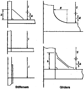
Fig 3.3.2 Definition of Span
108. Load point
The load point for which the design pressure in Ch 2 is defined for various strength members is as follows.
(1) Horizontally stiffened platings
Mid point of horizontally stiffened plating.
(2) Vertically stiffened platings
Half of the stiffener spacing above the lower support of vertically stiffened plating, or at the
lower edge of plating when the thickness is changed within
(3) Stiffeners
Mid point of span.
(4) Transverse or girders Mid point of load area.
the plating.
109. Buckling strength calculation
The buckling strength calculation is to be in accordance with
the Classification of Steel Ships.
Pt 3, Ch 3, Sec 4. of Rules for