Iranian Classification Society Rules

< Previous | Contents | Next >
Section 7 Transverses and Girders
701. General
1. Transverse arrangement
(1) Transverses are to be continuous around the cross section ; i.e., bottom, side and deck trans- verses, and have enough transverse strength.
(2) Transverse spacing, defined above in (1), is 4 times of Sr defined in 501, and bottom trans-
verse spacing is 2 times of .
2. Support of erections
In superstructures and deckhouses aft, the front bulkhead is to be in line with a transverse bulkhead in the hull below or be supported by a combination of partial transverse bulkheads, gird- ers and pillars.
702. Transverses and girders
1. The section modulus for transverses and girders supporting longitudinals, vertical frames, transverse beams or bulkhead stiffeners is not to less than that obtained from the following formula :
or
c
![]()
: for ship side only. It depends on whether or not cross ties support the side transverse, is
fitted or not.
= 1.0 where no cross tie is fitted.
: rise of floor correction factor, as in the following formula. R is not to be taken less 0.7.
than
and : as defined in Fig 3.3.5.

Fig 3.3.5
and
: bending moment factor, defined in Table 3.3.12.
= 10, average bottom, side, deck transverse, deck girders and vertical bulkhead webs.
= 12, average stringers.
allowable stress, defined in Table 3.3.9 for continuous longitudinal girder.
= 160, other girders.
material factor, defined in 501.
: girder or transverse span (m ).
: breadth of load area (m ), defined in following formula.
and : spans (m ) of the supported stiffeners
![]()
Table 3.3.12 Values of
and
Load and boundary conditions | Boundary moment and shear force factors | ||||
Positions | 1 | 2 | 3 | ||
1 Support | 2 Field | 3 Support |
|
|
|
| - |
| |||
12.0 | 24.0 | 12.0 | |||
0.50 | 0.50 | ||||
0.38 | 14.2 | 8.0 0.63 | |||
0.50 | 8.0 | 0.50 | |||
15.0 | 23.3 | 10.0 | |||
0.30 | 0.70 | ||||
0.20 | 16.8 | 7.5 0.80 | |||
0.33 | 7.8 | 0.67 | |||
2. The effective web area of transverses and stringers supporting longitudinals or other stiffeners
is not
to be less than that obtained from the
or
following formula :
cm
shear force factor, defined in Table 3.3.13, may be adjusted Table 3.3.12.
: factor, depended on whether cross ties is fitted or not, defined in Table 3.3.14.
, when no cross tie.
: span to a cross tie, when fitted.
: number of stiffeners between considered section and nearest support.
: average point load (kN) from stiffeners between considered section and nearest support.
allowable shear stress (N mm ).
= 120 (N mm ) for watertight bulkheads.
= 90 (N mm ) for elsewhere.
and : defined in above Par 1.
![]()
Cross tie fitted | No cross tie | |
Cross tie end | 0.5 | 1.0 |
Opposite end | 0.7 | 1.0 |
Table 3.3.13 Shear Factor ( Table 3.3.14 Factor (
Load | Lower end of vertical span | Upper end and horizontal span |
Slamming impact | 0.8 | 0.65 |
Other pressure | 0.75 | 0.55 |
703. Girders supporting other girders or pillar
1. The section modulus of girders supporting other girders or pillar is not to tained from the following formula :
be less than that ob-
cm
: load (kN) from supported girder or pillar.
: 5.5
: allowable stress (N mm ), as follows.
Continuous longitudinal girder : defined in Table 3.3.9.
Watertight bulkheads : 220 N mm
Other bulkheads : 160 N mm
2. The effective web area is not to be less than that obtained from the following formula :
c
: shear force factor, 0.55 at half- span.
704. Effective breadth of girders
The effective breadth of girders is to be in accordance with 601. Par 2.
705. Bottom transverses and girders
1. The scantlings of bottom transverses and girders
2. The center girder is normally to be fitted for
should comply with the requirements in 702.
docking purpose, if docking on a keel plating is
foreseen. The docking center girder is to have height, web thickness and flange area suitable for
the docking block load. The spacing of docking
brackets is to be less than , defined in 501.
3. Side girders for stabilizing purposes are normally to have spacing not exceeding 2.5 m . Forward of 0.25 from F.P. the spacing should not exceed 1.25 m if the rise of floor is less than 15°
4. In the engine room plate floor spacing is to be less than of , as defined in 501.
706. Side transverses and stringers
1. The scantlings of side transverses and stringers are to comply with the requirements in 702.
2. Vertical webs in the engine room and within 0.1 from the perpendiculars are to have a depth not less than that indicated in the following formula. It is not necessary to exceed 200 mm .
![]()
mm
: span of side transverse (m ).
3. In engine room and within 0.1 from A.P. the total flange width is not to be less than 35
707. Cross ties
Cross tie and panting beam scantlings are to be determined as for deck pillars, deck load being substituted by the supported craft side load.
708. Deck transverses and girders
1. The scantlings of deck transverses and girders are to comply with the requirements in 702.
2. For transverses in strength deck for > 50 m , supporting longitudinals subject to axial com- pression stresses the moment of inertia of the girder section (including effective plate flange) is not to be less than following formula. When > 100 N mm , the moment of inertia is to be in ac- cordance with the satisfaction of the Society.
cm
sectional area (cm ) of longitudinal including 0.8 plating
: flange. span (m ) of transverse.
distance (m ) between transverses.
:
spacing (m ) of longitudinals.
:
actual compressive stress (N mm ) estimated from hull girder strength calculation.
3. The depth of the deck transverse in the engine room is to be at least 50 % the depth of the side transverses, web thickness and face plate scantlings as for side transverses.
709. Bulkhead vertical webs and stringers
The scantlings of bulkhead vertical webs and stringers are to comply with requirements in 702.
710. End connections of girders
1. Normally, ends of single girders or connections between girders forming ring systems are to be provided with brackets. Brackets are generally to be radiused or well rounded at their toes. The free edge of the brackets is to be stiffened in accordance with Par 4.
2. The thickness of brackets on girders is not to be less than that of the girder web plating.
3. The arm length including depth of girder web may normally be taken as following formula :
mm
: rule section modulus (cm ) of the strength member to which the bracket is connected.
: thickness of bracket (mm ).
4. Flanges on girder brackets are normally to have a cross sectional area not less than that obtained from the following formula:
cm
![]()
: length of free edge of brackets (m ).
: defined in Par 3.
5. The thickness of the web plating at the cross joint of bracketless connections (refer to Fig 3.3.6), is not to be less than the greater of the following formulae.
mm
mm
: flange area (cm ) of girder 1 and
: bending stresses (N m m ) of girder 1
and 2.
: shear stresses (N mm ) of girder 1 and 2.
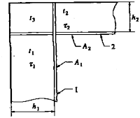
Fig 3.3.6 Bracketless Joint
711. Tripping brackets
1. The spacing ( ) of tripping brackets is normally not to exceed
2. Tripping brackets on girders are to be stiffened by a flange or
the values given in Table 3.3.15.
stiffener along the free edge if the
m
: thickness (m ) of tripping bracket.
The area of the stiffening is not to be less than that obtained from the following formula :
cm
length (m ) of free edge.
![]()
Table 3.3.15 Spacing between Tripping Brackets
Girder type | mm | |
Girders with s y mme t r ic a l face plate | - Bottom and deck transverses - Stringers, vertical webs and | 1.2 max. 6 m |
- Longitudinal girders in bottom and strength deck for 〉50 m within 0.5 amidships - Stringers and vertical webs in tanks and machinery spaces - Vertical webs supporting single bottom girders and transverses | 0.014 max. 4 m | |
Girders with unsymmetrical face plate | not more than 10 times the width of face plate max. 1.5 m | |
If the web of a strength member forms an angle with the perpendicular to the craft's side of less than 80°, is to exceed 0.007 | ||
NOTE : = flange breadth (mm ) = distance (m ) between transverse girders. | ||
712. Girder web stiffeners
The web plating of transverse and vertical girders
3.3.16.
are to be stiffened where, defined in Table
Table 3.3.16 Girder Web Stiffeners
Web height (mm ) | Max. spacing of stiffeners (mm ) | |
- Within 20 % of the span from each of the girder - Where high shear stresses |
|
|
- Elsewhere |
|
|
= web height (mm ). = web thickness (mm ). | ||