
< Previous | Contents | Next >
Section 7 Transverses and Girders
701. Applications
1. The scantling and arrangements of transverses and girders, not mentioned in this section, are to be in accordance with Ch 3, Sec 7.
2. Direct strength calculation of transverses is to be determined at the discretion of the Society.
702. Minimum thickness
The thickness of structures is normally not to be less than that obtained mula :
from the following for-
mm
Yield stress in N mm at 0.2% offset for unwelded alloy.
is not to be taken greater than 70% of the ultimate tensile
strength. actual stiffener spacing (m ).
: basic stiffener spacing, as following formula.
m
is not to be taken less than 0.5 or greater than
and : as defined in Table
703. Allowable stresses Maximum allowable bending
3.4.7.
stresses in transverses and girders are to be in accordance with Table
Table 3.4.6 Values of
and
![]()
Transverses and girders | |||
Bending stresses (N mm ) | Shear stresses (N mm ) | Equivalent stresses (N mm ) | |
Dynamic load | 180/ | 90/ | 200/ |
Sea/static load | 160/ | 90/ | 180/ |
Watertight bulkhead (excl. collision bulkhead) | 200/ | 100/ | 220/ |
Table 3.4.7 Allowable Stresses (
Structures |
|
| |
Girders and Stiffeners | Bottom center girder | 3.0 | 0.05 |
Bottom side girders, floors, brackets and stiffeners | 3.0 | 0.03 | |
Side, deck and bulkhead longi- tudinals girders and stiffeners outside the peaks | 3.0 | 0.02 | |
Peak girders and stiffeners | 3.0 | 0.03 | |
Longitudinals | 3.0 | 0.03 | |
Double bottom floors and girders | 3.0 | 0.02 | |
Other structures | Foundations | 3.0 | 0.08 |
Structures not mentioned above | 3.0 | 0.0 | |
![]()
704. Effective breadth
The effective breadth is to be in accordance with Ch 3, 601, Par 2.
705. Strength requirements
1. The section modulus of girders subjected to lateral pressure is not to be less than that obtained from the following formula :
cm
160/ (N mm
: ).
: breadth of load area (m ), defined in Table 3.4.8.
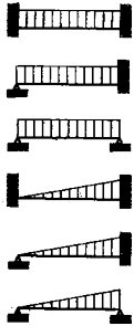
bending moment factor, defined in Table 3.4.9 and Table 3.4.10, for load and boundary conditions, and for not defined in previous Tables, m-values are directly from general elas-
: tic bending theory.
Table 3.4.8 Breadth of Load Area
| |
For ordinary girders | m |
For hatch side coamings | m |
For hatch end beams | m |
NOTE: and = the span (m ) of the supported stiffeners. = breadth of craft (m ) measured at the middle of hatchway. = breadth of hatch (m ) measured at the middle of hatchway. = distance (m ) between hatch end beam and nearest deep transverse girder or transverse bulkhead. | |
2. The effective web area of girders subjected to lateral pressure is not to be less than that obtained from the following formula :
cm
shear force factor, defined in Table 3.4.9 and 3.4.10.
: number of stiffeners between considered section and nearest support, however, the - value
: is in no case to be taken greater than ( +1)/4.
: Girder span
number of supported stiffeners on the girder span, however, the web area at the middle of
: the span is not to be less than 0.5 .
: average point load (kN) from stiffeners between considered section and nearest support.
3. The equivalent stress is not to be exceed 180/ .
4. Tripping brackets
![]()
The tripping brackets are to be in accordance with requirements in Ch 3, 711.
![]()
5. Girder web stiffeners
The girder web stiffeners are to be in accordance with requirements in Ch 3, 712.
Table 3.4.9 Values of
and
Load and boundary conditions | Boundary moment and shear force factors | ||||
Positions | 1 | 2 | 3 | ||
1 Support | 2 Field | 3 Support |
|
- |
|
85 | 42 | 85 | |||
0.50 | 0.50 | ||||
0.38 | 70 | 125 0.63 | |||
0.50 | 125 | 0.50 | |||
65 | 43 | 100 | |||
0.30 | 0.70 | ||||
0.20 | 60 | 135 0.80 | |||
0.33 | 130 | 0.67 | |||

Table 3.4.10 Factors
and
|
| ||
Bottom | Transverses Floors Longitudinal girders | 100 | 0.63 |
Side | Longitudinal girders Transverses, upper end Transverses, lower end Deck girders | 100 | 0.54 0.54 0.72 0.63 |
Bulkhead | Horizontal girders Vertical girders, upper end Vertical girders, lower end | 100 | 0.54 0.54 0.72 |