< Previous | Contents | Next >
Section 3 Power Supply
301. General
1. All electrical equipment essential for the safety of the submersible and its crew is to be connected to an independent main and emergency power supply system.
2. In the case of surface-dependent submersibles the main power supply may be followed directly from the switchboard of the diving support vessel and/or from the main power source of the diving system.
3. The followings may be used as an independent emergency power source:
(1) An electrical generator with its own drive
(2) An emergency battery of sufficient capacity
4. The power generating and emergency supply equipment is to be so designed that the voltage and frequency variations allowed by the provisions of Pt 6, Ch 1, Table 6.1.1 of Rules for the Classification of Steel Ships.
5. The power requirements of the submersible when at sea are to be determined for both underwater and surface navigation.
302. Main power supply
1. Each submersible equipped with a main power source of sufficient capacity to supply the items of equipment mentioned in Pt 6, Ch 1, 201. 2 of Rules for the Classification of Steel Ships. It is to be designed to ensure a sufficient supply of electrical power for the proposed period of serv- ice when operation is both independent of and dependent on an outside air supply.
2. The main power source is to consist of at least two mutually independent generator sets or of one generator set and a battery of sufficient capacity. The battery is to be capable of being charged from at least one generator set. Exceptions may be permitted in the case of vehicles with a re- stricted range of service and/or accompanying support vessels.
3. Generator sets with electrical starting equipment are to be provided with a starter conforming to
Pt 5, Ch 2, 202. 5 of Rules for the Classification of Steel Ships.
303. Emergency power supply
1. An independent emergency power source is to be provided in all submersibles.
2. The emergency power source is to be capable of supplying the submersible with the energy re- quired in emergencies. All electrical equipment required for surfacing the vessel is to be adequately
supplied with power; apart from this, simultaneous supply of electrical power to at least
ment listed below is to be ensured for the periods specified in Ch 14, 201.
(1) Emergency lighting inside the vehicle
![]()
(2) Emergency communications equipment
the equip-
![]()
(3) Equipment for maintaining a breathable atmosphere
(4) Important monitoring and alarm equipment, e.g. leakage monitoring system, fire alarm system,
O2 monitor and H2 monitor
(5) Solenoid valves for blowing diving and reserve buoyancy tanks
(6) Stand-by pumps for freeing the diving tanks (where fitted, for freeing the diving tanks 1.5 times at nominal diving depth)
(7) Locating equipment, signal lamps.
3. In addition, in autonomous submersibles it is to be possible to supply electricity to the wireless equipment and important navigating equipment for at least 18 hours of operation.
304. Charging and shore connection
1. Where socket connections are provided for charging and shore connection, these are to be so de- signed that the plugs cannot be inserted or withdrawn on load.
2. The submersible is to be provided with a control switch enabling the supply switch of the shore or charging station to be disconnected.
305. Storage batteries
1. Storage batteries providing a power source for electric propeller drives and/or the vehicle's power network should be accommodated in special battery spaces. It is necessary to ensure that the stor- age batteries are accessible for cell replacement, for repairs and maintenance.
2. Battery spaces are to be arranged and ventilated to prevent the accumulation of ignitable gas mixtures.
3. The quantity of air to be aspirated and exhausted during charging is to be so calculated, as to ex- clude any possibility of exceeding the lower explosion limit for a hydrogen air mixture. H2 mon- itors permanently mounted at suitable points are to measure the gas concentration in the battery space, the exhaust system and, where necessary, in other spaces within the vehicle. If the gas con- centration reaches and exceeds a level equivalent to 35 % of the lower explosion limit, this shall automatically release a visual and audible alarm at a central monitoring station. Equipment for monitoring the H2 concentration is to be type tested.
4. Battery spaces may contain no other electrical appliances apart from the storage batteries themselves and light fixtures with at least T1(Exe T1) class enclosure. Switches, sockets, junction boxes etc.
are to be placed outside battery spaces. The installation of battery monitoring
equipment, e.g. H2
monitors with T1 (Exi T1) class enclosure, is permitted. Single-cell fuses for the voltage measuring system are permitted with T1 (Exd IIC T1) type enclosure.
5. Measures are to be taken to ensure that neither the crew nor the operational equipment can be en- dangered by emissions of electrolyte fumes.
6. A sign is to be mounted at the entrance of battery spaces pointing out that only insulated tools are to be used inside and conductive objects like keys, ballpoint pens, watches with conductive watch straps have to be taken off. Attention is to be drawn to the explosion hazard.
7. Storage batteries are to be installed in such a way that mechanical damage excluded. Safe operation under the environmental conditions stated in Ch 4,
is as far as possible
Sec 2. is to be en-
sured and the discharge of electrolyte is to be prevented. Suitable measures, e.g. provision of plas-
tic trays or flexible rubber bags, are to be taken to prevent, wherever possible, electrolyte from en- tering the battery space bilges in the event of mechanical damage to individual battery cells.
8. Where the installed battery capacity is 1000 AH or more, the battery is to be divided into smaller battery units so that restricted operation of the submersible is still possible in the event of a fault.
9. Lead and alkaline storage batteries may not be accommodated in the same space or be placed in direct proximity to each other.
10. The design of storage batteries and battery chargers is complied with Pt 6 of Rules for the Classification of Steel Ships.
![]()
11. Battery chargers are to cut out automatically in case of :
(1) Failure of battery space ventilation
(2) Excessive temperature of charging generator.
(3) Excessive H2 concentration.
306. Power distribution
1. Distribution and switchgear
(1) Electrical distribution systems are to be so designed that a fault or failure in one circuit cannot impair the operation of other circuits or the power supply.
(2) In normal operation, the emergency power distribution system may be supplied via a transfer line from the main power distribution system.
(3) Switchboards are to be so placed as to minimize the length of the cables connecting all the
storage batteries to the board. These cables are to be laid as far as their respective circuit breakers in separate cable runs and are to be protected against mechanical damage.
(4) Effective measures are to be taken to prevent the occurrence of vagabond voltages inside
switchgear. Circuits at protective low voltage may not be routed with circuits at higher voltage in a joint conductor bundle or cable duct. Terminals for different voltage levels are to be ar- ranged separately and are to be clearly identified.
(5) Switches and fuses for different voltage systems are to be spatially separated inside the switchboard.
2. Switching and protective devices
(1) Each circuit is to be protected against overload and short circuit.
(2) All consumer circuits are to be fitted with switches. The switching action is to be on all poles.
(3) Fuses may be used for overload protection on submersibles up to a rated current of 63 A.
(4) A continuously operating insulation monitoring system is to be installed. An alarm is to be trip- ped at the control platform if the insulation value drops below a preset limit.
3. Enclosures for electrical equipment
(1) The enclosures of electrical equipment installed outside the pressure hull or operated in water is to be approved by this Society.
(2) Enclosures mounted on the outside of the pressure hull are to be tested at the test diving pres-
sure, subject to a minimum of 1.3 times the design pressure.
4. Earthing
(1) Earthing arrangements on surface-dependent submersibles are subject to the requirements in Pt 6
of Rules for the Classification of Steel Ships.
(2) The earthing of electrical systems and equipment on autonomous submersibles is subject to the requirements stated in Pt 9, Ch 7, 1204. 4 of Rules for the Classification of Steel Ships.
5. Cables and lines
(1) Cables and lines for submersibles are to be approved by the Society.
(2) The selection, dimensions and installation of cables and lines shall comply with the Pt 6 of
Rules for the Classification of Steel Ships.
(3) Only halogen-free materials should be used as and fillers of cables used in submersibles.
(4) Underwater cables and lines are to be radially
static pressure equal to the destructive pressure to be verified by pressure testing each made up
insulating sleeves, protective coverings, sheaths
watertight and designed for an external hydro- of the pressure hull. The pressure resistance is length after the connectors have been fitted.
(5) Electric umbilicals are to be tested in the manufacturer's works in the presence of the surveyor.
(6) In cables for winding on drums, no mechanical forces may be transmitted via conductors of the cable and their insulation.
6. Busbars
(1) Where busbars are used for connecting equipment, only sealed or insulated systems may be employed. Exceptions to this Rule are switchboards and enclosed electrical service spaces.
(2) The loading of busbars is to conform to the requirements of Pt 6 of
Classification of Steel Ships. On continuous load, the busbar temperature
Rules for the
may not exceed
![]()
100°C.
(3) The busbar system is to be so constructed that neither the connected equipment nor the busbar system itself can be damaged by movement of the busbars, temperature rises or external me- chanical influences. It is recommended that expansion links should be fitted. Prior to the in- stallation of busbar systems, proof is of mechanical strength under short-circuit considering the effects of the electrical heating produced by the short-circuit current.
(4) Only copper with a conductivity of 56 mĤŌmmË may be used for busbars. If other conducting materials are used, the loading capacity of the system is to be reduced accordingly.
7. Electrical penetrations in pressure hull walls, underwater plug connections
(1) Pressure hull penetrations are to be gas and watertight. Their tightness is to be guaranteed even should the connected cables be damaged or shorn off. Electrical penetrations may not be used for the passage other systems.
(2) Electrical pressure hull penetrations and underwater plug connections are to be type tested. Type testing is performed, on application, at the manufacturer's works and comprises at least the fol-
lowing tests:
(a) Hydraulic pressure test, in which the test pressure is to equal twice the design pressure. The test is to be conducted in accordance with the test pressure/time curve shown in Fig.
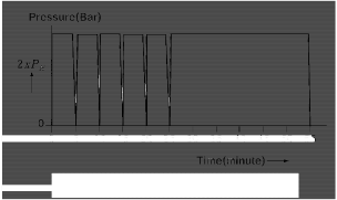
1.12.1, the changes in pressure being applied as quickly as possible.
Fig 1.12.1 Test pressure/time curve
(b) Gastightness test with shorn, open cable ends. This test may be performed alternatively un- der air or helium pressure. If compressed air is used, the test pressure is to equal twice the design pressure; if helium is used, 1.5 times. In all pressure and tightness tests on pressure hull wall penetrations, the pressure is to in each case be applied from the pressure side of the wall penetration.
During the pressure and tightness test, the penetration is to be loaded with the rated current in all conductors.
(c) High voltage test at an AC voltage of 1000 V plus twice the rated
voltage. This test is performed at the rated frequency and is to be carried out for 1 minute in each case between all the conductors mutually and between the conductors and the casing. The test is performed in the disconnected state. The sealing of the conductors shells and the like is permitted where this is stipulated by the manufacturer in the relevant data sheet.
(d) Measurement of insulation resistance. The minimum value of the insulation resistance be- tween the conductors mutually and between the conductors and the casing shall be 5 MW. The insulation resistance is to be measured with an instrument using 500 V DC. With wet plug connections, the minimum insulation resistance is also to be measured after the con- nection has been made once in saltwater.
(e)
Visual check against manufacturer's documentation.
(3) All electrical pressure hull wall penetrations and all plug connections are to be subjected to in- dividual vidual inspection by the manufacturer. This inspection comprises the following tests:
(a)
Hydraulic pressure test in accordance with Fig. 1.12.2 at 1.5 times the rated pressure.
(b) High-voltage test
(c)
Measurement of insulation resistance
A manufacturer's test certificate is to be issued covering the inspection.
![]()
Fig 1.12.2 Test pressure/time curve

307. Electrical machines
1. Electrical machines are to be complied with Pt 6, Ch 1 of Rules for the Classification of Steel Ships.
2. Generators with an output of 100 kVA and all electric propeller motors rated at over 100 kW are to be equipped with a standstill heating system.
3. Machines for electric propeller drives rated at more than 100 kW are to be equipped with monitor- ing devices in accordance with Pt 6, Ch 1 of Rules for the Classification of Steel Ships.
4. Insulation classes A and E are not permitted the windings of electrical machines in submersibles.
5. In addition to the tests stipulated in Pt 6, Ch 1 of Rules for the Classification of Steel Ships
the following electrical machines are to be tested in the presence of the Surveyor:
(1) Generators and motors for electric propeller drives
(2) Motors for steering gear drives and windlasses
(3) All other motors driving machines and equipment necessary to the safety and manoeuvrability of the submersible.
308. Interior lighting
1. Service and work spaces, safety and control stations, accommodation spaces and day rooms are to be equipped with normal and emergency lighting.
2. The lighting is to be so designed and arranged that all important instruments and markings can be read and any necessary operations can be safely performed.
309. Spare parts
1. Autonomous submersibles are to be provided with spare parts in
for the Classification of Steel Ships.
2. Relaxations can be permitted in the case of submersibles which with, or are supplied by, accompanying surface vessels. ![]()
accordance with Pt 6 of Rules
can only operate in conjunction
![]()