Iranian Classification Society Rules

< Previous | Contents | Next >
Section 4 Calculation of Strength
401. Structural analysis
The unit is to be analysed by the method deemed appropriate by the Society for a sufficient num- ber of conditions including all conditions specified in Ch 1, 107.
402. Analysis of units resting on the sea bed
Units designed to rest on the sea bed are to be analysed assuming the overturning moment due to the combined environmental forces from any direction and the sufficient downward gravity loadings on the support footings or mat to withstand the moment.
403. Plastic analysis
Scantlings of structural members designed on the basis of plastic analysis are to be at the dis- cretion of the Society.
404. Buckling strength
Structural members subject to in-plane loads are to have the sufficient strength against buckling in consideration of their shapes, scantlings, boundary conditions, etc.
405. Fatigue strength
1. The possibility of fatigue damage due to cyclic loading should be considered in the design of self-elevating and column-stabilized units.
2. The area anticipated stress concentration is to be considered to fatigue strength, the fatigue analysis is to be based on the intended mode and area of operations to be considered in the unit's design.
3. The fatigue life is to be based on a period of time equal to the specified design life of the unit.
The period is normally not to be taken as less than 20 years.
406. Stress concentration
1. The effect of local stress concentrations is to be considered for notches in members or dis- continuous parts of structure.
2. Where the tensile stresses acting on the thickness direction of plating, plate material with suitable
through-thickness properties is required in accordance with Pt 2, Classification of Steel Ships.
Ch 1 of Rules for the
407. Bending stress
1. When calculating bending stresses of structural members, the effective width of the plate is to be
determined in accordance with the requirements in Pt 3, Ch 1, 602. of Rules Classification of Steel Ships.
for the
2. Where subjected to eccentric loadings, an increase of bending stress due to the deflections of the structural members is to be taken into account.
408. Shearing stress
When calculating shearing stresses in bulkheads, plate girder webs, hull side plating, etc., only the effective shear area of web is to be considered as being effective. In this regard, the total depth of the girder may be considered as the web depth.
409. Combination of stresses
1. In obtaining respective local stresses of the structural members, all the stress components concerned
![]()
are to be summed up. In this case, for tubular members, the effect of circumferential stress due to external pressure is to be considered.
2. The scantlings are to be determined on the basis of criteria which combine, in a rational manner deemed appropriate by the Society, the individual stress components acting on the respective struc- tural members.(See 410.)
410. Equivalent stress
1. For plate structures, members may be designed according to the equivalent stress criterion, where the equivalent stress is obtained from the following formula.
, : Stress in the - and -directions at the centre of thickness of the plate, respectively
: Shearing stress in the plane(N mm
2. The equivalent stress specified in Par 1 is not to exceed 0.7 and 0.9 times the yield strength of the material, for the static loading and combined loading condition specified in 412., respectively.
411. Corrosion allowance
1. In case where the unit is fitted with a corrosion protection system deemed appropriate by the Society, with regard to the corrosion allowance specified in Par 2 reduction may be made as deemed adequate by the Society.
2. Where the unit is not fitted with a corrosion protection system deemed appropriate by the Society, the scantlings determined by the analysing method and the allowable stresses specified in this chap-
ter are to be added by a proper corrosion allowance. In this case, the rule, not to be less than 2.5 mm and is to be determined considering
corrosion allowance is, as a the environmental condition,
the means and degree of corrosion protection specified in Sec 17 and the process of its
maintenance. And further, where the requirements in Rules for the Classification of Steel Ships
or Rules for the Classification of Steel Barges are applied, the scantlings are not to be less
than those specified in the relevant requirements.
412. Analysis of Overall Strength
1. Loading conditions
Analysis of overall strength is to be performed for the static loading and combined loading speci- fied in the following (1) and (2) in the respective modes of operation specified in Ch 1, 107.
(1) The static loading is a condition in which the unit is afloat or resting on the sea bed in calm sea and is loaded with static loads only such as loads taken in operating condition, dead load
of the unit, etc. which affect the overall strength.
(2) The combined loading is a condition in which the unit is loaded with combined loads of the static loads specified in (1), and dynamic loads such as wind loads, wave loads, etc. which af- fect the overall strength and loads induced by the accelerative motion of the unit due to these loads and heeling.
2. Allowable stresses
Allowable stresses for static loading and combined loading specified in Par 1 are not to exceed the values in Table 3.2 according to the kind of stress.
3. Combined compressive stress
In addition to Par 2, when structural members are subjected to axial compression or combined ax- ial compression and bending, the extreme fibre stresses shall comply with the following require- ment:
![]()
≤
: Calculated compressive stress due to axial force(N mm
: ).
: Allowable compressive stress due to bending prescribed in Table 3.2 (N mm ).
: Allowable axial compressive stress obtained from the following
formula, but is not to exceed
(N mm )
× × ×
......................
: As specified in Par 2 (N mm
: Inelastic column critical buckling stress (N mm
).
= 0.6 for static loading
= 0.8 for combined loading
= Effective unsupported length (m )
= Governing radius of gyration associated with (m
)
Table 3.2 Allowable Stresses for Static Loading and Combined Loading
Kind of stress | Static loading | Combined loading | |||
Tensile | 0.6 × | 1.8 | |||
Bending | 0.6 × ( | or | * ) | 0.8 × | or * ) |
Shearing | 0.4 × | or | 0.6 × * | 0.53 × | or 0.8 × * |
Compressive | 0.6 × ( | or | * ) | 0.8 × | or *) |
* : Whichever is the smaller
: ). : Critical compressive buckling stress (N mm | |||||
413. Scantlings of Structural Members
1. General
(1) For the primary structural members which contribute to the overall strength, the scantlings are to be determined in accordance with the requirements in Sec 2 and 3. However, the require- ments in 401. and 412. may be applied.
(2)
![]()
For the structural members subjected to local loads only, the requirements in Rules for the Classification of Steel Ships may be applied under the approval of the Society.
![]()
2. Thickness of plating of hull structure
The thickness of plating of the primary hull structure such as shell plating which contributes to the overall strength, subjected to distributed loads, is not to be less than obtained from the following formulae, whichever is the greater.
mm
Spacing of transverse or longitudinal frames(m ).
: Head of water in static loading specified in 412. 1.(m ).
Head of water in combined loading specified in 412. 1.(m ).
:
As given by the following formulae, whichever is the smaller.
: As given in (a) or (b) below.
(a) Where × , the value given by the following formulae, whichever is the
(b) Where × , the value given by the following formulae, whichever is the
and ,
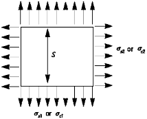
: Axial stresses acting on the plating in static loading and com-
bined loading, respectively (N mm ). (See Fig
![]()
Fig 3.1 Axial stress ,
![]()
: Material factor, as given in the following.
Mild steels 1.00
High tensile steels
A 32, DH 32, EH 32 0.78
AH 36, DH 36, EH 36 0.72
For other high tensile steels, the value of k is to be dedicated at the discretion of the Society.
: Corrosion allowance specified in 411.
3. Section modulus of transverse or longitudinal frames
The section modulus of transverse or longitudinal frames which support the panels prescribed in
Par 2 is to be obtained from the following formula.
cm
: Coefficient given below.
1.0 for both ends fixed
1.5 for both ends simply supported
:
:
, ,
Span of frames (m ).
Axial stress in combined loading (N mm
).
4. Local buckling of cylindrical shells
Unstiffened or ring-stiffened cylindrical shells subjected to axial compression, or compression due to bending, and having proportions which satisfy the following relationship are to be checked for local buckling in addition to the overall buckling as specified in 412. Par 3.
: Diameter of cylindrical shell
: Thickness of shell plating
( and expressed in the same
: Specified minimum yield stress of the material
: Modulus of elasticity of the material
414. Helicopter Deck
1. Design loads
Plans showing the arrangement, scantlings and details of the helicopter deck are to be submitted. The arrangement plan is to show the overall size of the helicopter deck and the designated landing area. The design load in determining the scantlings of the members of helicopter deck is to be in accordance with following (1) to (3).
(1) Helicopter landing impact loading
(A) As for the deck loads in the range where a helicopter takes off or lands, a load of 75 % of the helicopter maximum take-off weight is to be taken on each of two square areas, 0.3
m × 0.3 m .
![]()
(B) For girders, stanchions, etc., the structural weight of the helicopter deck is to be considered in addition to the helicopter impact loading specified in (A).
(C) Where the upper deck of a structure or deck house is used as a helicopter deck and the
spaces below are normally manned, the impact loading specified in (A) is to be multiplied by a factor of 1.15.
(2) Stowed helicopter loading
(A) The deck loads in the space where a helicopter is stowed are to be taken as wheel load- ings at maximum take-off weight. In this case, the dynamical effect due to the motion of the unit is also to be taken into account.
(B) In addition to (A), a uniformly distributed loading of 0.5 kN m , representing wet snow or ice is to be considered, if necessary.
(C) For girders, stanchions, etc., the structural weight of the helicopter deck is to be considered
in addition to the loads specified in (A).
(3) Minimum deck load
The minimum deck load for helicopter deck is to be taken as 2 kN m .
2. Allowable stresses
Allowable stresses of the structural members of the helicopter deck are not to exceed the values in
Table 3.3 in association with the design loads prescribed in Par 1.
![]()
Table 3.3 Allowable Stresses
Structural members Design loads | Deck plating | Deck beams | Girders, stanchions, truss supports, etc. |
Helicopter landing impact load | * |
| 0.9 × ′ |
Stowed helicopter load |
| 1.9 × | 0.8 × ′ |
Overall distributed load | 0.6 × | 0.6 × | 0.6 × ′ |
* : At the discretion of the Society. : As specified in 412. 1. (N mm ). ′ : For members subjected to axial compression, or critical buckling stress, whichever is the smaller(N mm | |||
3. Minimum thickness
The minimum thickness of helicopter deck plating is not to be less than 6 mm .
4. Landing appliances other than wheels
In case where a helicopter is provided with any other landing appliances other than wheels, the de- sign loads are to be at the discretion of the Society.
5. Loadings on helicopter deck
Wind loadings and possible wave impact loadings on helicopter decks are to be considered. Where in this case, those loadings are in accordance with the discretion of the Society.
415. Position Keeping Systems and Components
1. General
Units provided with position keeping systems equipment in accordance with this Section may have a Additional Installation Notation, "PKS" after the class notation.
2. Anchoring systems
(1) General
Plans showing the arrangement and completed details of the anchoring system, including an- chors, shackles, anchor lines consisting of chain, wire or rope, together with details of fairleads, windlasses, winches, and any other components of the anchoring system and their foundations are to be submitted to the Society.
(2) Design
![]()
(A) An analysis of the anchoring arrangements expected to be utilized in the unit's operation is
![]()
to be submitted to the Society. Among the items to be addressed are:
(a) Design environmental conditions of waves, winds, currents, tides and ranges of water depth
(b) Air and sea temperature
(c)
Ice condition (if applicable)
(d) Description of analysis methodology
(B) The anchoring system should be designed so that a sudden failure of any single anchor line will not cause progressive failure of remaining lines in the anchoring arrangement.
(C) Anchoring system components should be designed utilizing adequate factors of safety and a
design methodology suitable to identify the most severe loading condition for each component. In particular, sufficient numbers of heading angles together with the most severe combination of wind, current and wave are to be considered, usually from the same direc- tion, to determine the maximum tension in each mooring line. When a particular site is be-
ing
considered, any applicable cross sea conditions are also to be considered in the event
that they might induce higher mooring loads.
(a)
When the Quasi Static Method is applied, the tension in each anchor line is to be cal- culated at the maximum excursion for each design condition defined in (b) below, com- bining the following steady state and dynamic responses of the Unit:
(ⅰ) steady mean offset due to the defined wind, current, and steady wave forces
(ⅱ) most probable maximum wave induced motions of the moored unit due to wave
excitation
For relatively deep water, the effect from damping and inertia forces in the anchor lines is to be considered in the analysis. The effects of slowly varying motions are to be in- cluded when the magnitudes of such motions are considered to be significant.
(b) Factors of safety (FOS) are dependent on the design conditions of the system (intact, damaged, or transient), as well as the level of analyses (Quasi static or dynamic analy- sis). The minimum Quasi Static FOS, specified in the table below, at the maximum ex- cursion of the unit for a range of headings should be satisfied if the quasi static meth-
od outlined in (a)
is applied. Otherwise, the minimum Dynamic Analysis FOS in the
The (c)
Table 3.4 should be satisfied, including the effects of line dynamics when these effects are considered significant.
defined 'Operating' and 'Severe Storm' are to be the same as those identified for the design of the unit, unless the Society is satisfied that lesser conditions may be appli-
cable to specific sites.
In general, the maximum wave induced motions of the moored unit about the steady
mean offset should be obtained by means of model tests. The
Society may accept ana-
lytical calculations provided that the proposed method is based on a sound methodology which has been validated by model tests.
In the consideration of column-stabilized units, the value of and , as indicated
Ch 4, 201. may
The intent of Ch
be introduced in the analysis for position keeping mooring systems.
4, 302. 3(Wind tunnel test) and of Ch 4, 302. 4(Other stability re-
quirements) may also be considered by the Society.
(d) The Society may accept different analysis methodologies provided that it is satisfied that a level of safety equivalent to the one obtained by (a) and (b) above.
(e)
The Society may give special consideration to an arrangement where the anchoring sys-
![]()
tems are used in conjunction with thrusters to maintain the unit on station.
![]()
Table 3.4 Anchor Line FOS
Design Condition | Anchor Line FOS | ||
Quasi Static | Dynamic Analysis | ||
Operating | Intact | 2.70 | 2.25 |
Damaged | 1.80 | 1.57 | |
Transient | 1.40 | 1.22 | |
Severe Storm | Intact | 2.00 | 1.67 |
Damaged | 1.43 | 1.25 | |
Transient | 1.18 | 1.05 | |
where, max = maximum rated breaking load of the weakest component of the anchor line. max = maximum anchor line tension calculated in accordance with (C) or Section 5.1.3.2 of API RP 2SK for each of the following design conditions. (a) Operating Intact: max determined under the most severe design environmental conditions for normal operations specified by the Owner or designer with all anchor lines intact. (b) Operating Damaged: max , under the operating environmental conditions specified above, but assuming the sud- den failure of any one anchor line, after reaching a steady-state condition. (c) Operating Transient: max , under the operating environmental conditions specified above, due to transient mo- tions resulting from the sudden failure of any one anchor line. (d) Severe Storm Intact: max determined under the most severe design environmental conditions for severe storm specified by the Owner or designer with all anchor lines intact. (e) Severe Storm Damaged: max , under the severe storm environmental conditions specified above, but assuming the sudden failure of any one anchor line, after reaching a steady-state condition. (f) Severe Storm Transient: max , under the severe storm environmental conditions specified above, due to tran- sient motions resulting from the sudden failure of any one anchor line. | |||
3. Equipment
(1) Windlass
(A) The design of the windlass is to provide for adequate dynamic braking capacity to control normal combinations of loads from the anchor, anchor line and anchor handling vessel dur- ing the deployment of the anchors at the maximum design payout speed of the windlass. The attachment of the windlass to the hull structure is to be designed to withstand the breaking strength of the anchor line.
(B) Each windlass is to be provided with two independent power operated brakes and each brake is to be capable of holding against a static load in the anchor lines of at least 50 percent of its breaking strength. Where the Society so allows, one of the brakes may be re-
placed by a manually operated brake.
(C) On loss of power to the windlasses, the power operated braking system should be automati- cally applied and be capable of holding against 50 percent of the total static braking ca- pacity of the windlass.
(2) Fairleads and sheaves
Fairleads and sheaves should be designed to prevent excessive bending and wear of the anchor
lines. The attachments posed when an anchor
4. Anchor line
(1) The Society is to be
to the hull or structure are to be such as to withstand the stresses im- line is loaded to its breaking strength.
ensured that the anchor lines are of a type that will satisfy the design
![]()
conditions of the anchoring system.
![]()
(2) Means are to be provided to enable the anchor lines to be released from the unit after loss of main power.
(3) Means are to be provided for measuring anchor line tensions.
(4) Anchor lines are to be of adequate length to prevent uplift of the anchors under the maximum design condition for the anticipated area(s) of operation. However, only steady wind, wave and current forces need to be applied in evaluating anchor uplift forces in transient conditions.
5. Anchors
(1) Type and design of anchors are to be to the satisfaction of the Society.
(2) All anchors are to be stowed to prevent movement during transit.
6. Quality control
Details of the quality control of the manufacturing process of the individual anchoring system com- ponents are to be submitted. Components should be designed, manufactured and tested in accord- ance with recognized standards insofar as possible and practical. Equipment so tested should, insofar as practical, be legibly and permanently marked with the Society's stamp and delivered with doc- umentation which records the results of the tests.
7. Control stations
(1) A manned control station is to be provided with means to indicate anchor line tensions at the individual windlass control positions and to indicate wind speed and direction.
(2) Reliable means are to be provided to communicate between locations critical to the anchoring
operation.
(3) Means are to be provided at the individual windlass control positions to monitor anchor line tension, windlass power load and to indicate amount of anchor line payed out.
8. Dynamic positioning systems
Thrusters used as a sloe means of position keeping should provided a level of safety equivalent to that provided for anchoring arrangements to the satisfaction of the Society.