Iranian Classification Society Rules

< Previous | Contents | Next >
Section 2 Pressure Adjusting Factors
201. General
Final design pressure is adjusted by a set etc.
of factors according to design, craft type and location,
202. Design category factor, ÝǼÆ
The design category factor ÝǼÆ , defined in loads due to sea with design category.
Table 4.1, takes into account the variation of pressure
Table 4.1 Values of ÝǼÆ
according to design category
Design category | A | B | C | D |
ÝǼÆ | 1 | 0.8 | 0.6 | 0.4 |
203 Dynamic load factor,
1. General
The dynamic load factor
ŸÆĂ
ŸÆĂ
is considered to be close to the single amplitude acceleration meas-
ured at the craft centre of gravity at the relevant frequency for a certain period of time. This fac-
tor is the negative acceleration supported by the craft, either while slamming in an encountered
wave at speed or falling from the crest of a wave into its trough. g is the acceleration due to gravity (9.81 mĤsË).
ŸÆĂ
is expressed in gs where 1
2. Dynamic load factor
ŸÆĂ for planing non-sailing craft in planing mode
The dynamic load factor for planing craft running in planing mode shall be determined from Equation (1) or Equation (2).
ÄBÄ
à Ë× A Ë
Æ
Æ
ŸẄX G ŊĦĖËF JËŊ ×A Ğ ŊĦŊĒĖF×FÈŊGØŊĦĖF× ŶJ
ÄǼÆ
(1)
where,
V : for non-sailing craft, the maximum speed in calm water declared by the manufacturer, with
the craft in ŶÄǼÆ conditions. This speed shall not be taken as <
ËĦĖÈĬJÄBÄ .
AÆ : the chine beam, measured at
12215-5 Fig 1)
ŊĦĖĬJÄ BÄ
forward of its aft end, in metres (See ISO
ØŊĦĖ : the deadrise angle at
ŊĦĖĬJÄ BÄ
forward of its aft end (See ISO 12215-5 Fig 1), not to be
taken < 10°, nor > 30°, in degrees,
Where Equation (1) gives an Where Equation (1) gives an used.
ŸÆĂ value ≤ 3.0, the value given by Equation (1) shall be used.
ŸÆĂ value > 3.0, that value or the value from Equation (2) shall be
Ÿ ŊĦÈ×à (2)
ÆĂ G JĦËĒŊ
ŶÄǼÆ
In any case,
ŸÆĂ need not be taken > 7.
Ch 4 Structures Ch 4
![]()
3. Dynamic load factor ŸÆĂ for sailing craft and displacement non-sailing craft
For sailing craft, ŸÆĂ
is not used for pressure determination. It is only used in the calculation of
ÝÄ for which purpose the value of
ŸÆĂ
shall be taken as 3. For non-sailing craft where ŸÆĂ, de-
termined using Equation (1), is < 3.0 from Equation (1), a value of 3.0 shall still be used for cal-
culation of ÝÄ .
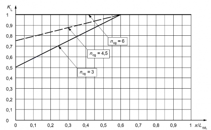
4. Longitudinal pressure distribution factor ÝÄ
The longitudinal pressure distribution factor ÝÄ takes into account the variation of pressure loads due to location on the craft. It shall be taken from Fig 4.2 or calculated from Equation (3).
ÝÄ is a function of the dynamic load factor defined below for non-sailing craft.
ËG ŊĦËÈĒ× ŸÆĂ Ż Ż
ÝÄ G JŊĦÈ
JÄ Ğ ŊĦËÈĒ × ŸÆĂ but not taken > 1 for JÄ
≤ŊĦÈ (3)
ÝÄ G Ë for
Ż JÄBÄ
BÄ BÄ
IŊĦÈ
where
ŸÆĂ is determined in accordance with 1 to 3, but for the purposes of determination of ÝÄ , shall not be taken < 3 nor > 6;
ŸÆĂ
Ż JÄBÄ
is the position of the centre of the panel or middle of stiffener analysed proportional to
Ż
ÄBÄ, where
JÄBÄ
= 0 and 1 are respectively the aft end and fore end of ÄBÄ.
where
Ż is the longitudinal position of the centre of the panel or middle of stiffener forward of
aft end of
ÄBÄ in
ŶÄǼÆ
conditions, in metres.
The overhangs waterline.
fore and aft shall have the same value of ÝÄ as their respective end of the
Fig 4.2 Longitudinal pressure distribution factor ÝÄ
Ch 4 Structures Ch 4
![]()
204. Area pressure reduction factor
1. General
The area pressure reduction factor panel or stiffener size.
ÝAĄ
ÝAĄ
takes into account the variation of pressure loads due to
ÝĄ × ŊĦË× ŶÄǼÆ Ŋ
Ǽ
ÝAĄ G JA ŊĦĖ
ĦËÈ
(4)
where
ÝĄ is the structural component and craft type factor:
ÝĄ G ËĦŊ
for bottom side and deck panels and stiffeners of planing non-sailing craft operating in planing mode;
ÝĄ G ËĦÈ G
G Ė
Ė× ËŊ × Ẅ
for bottom side and deck panels of sailing craft, displacement non- sailing craft and planing non-sailing craft operating in displace- ment mode;
ÝĄ G Ë G Ë×
G Ė
ËŊ ×ŶŹ
for bottom side and deck stiffeners of sailing craft, displacement
non-sailing craft and planing non-sailing craft operating in ment mode;
AǼ is the design area, in square metres:
AǼ G FŶ× ẄF × ËŊG È for plating, but shall not be taken > ËĦÈ× ẄË × ËŊG È;
G È Ë G È
displace-
AǼ G FŶŹ ×ZF × ËŊ
for stiffeners but need not be taken < ŊĦĖĖ × ŶŹ × ËŊ ;
Ẅ is the shorter dimension of the panel, in millimetres; Ŷ is the longer dimension of the panel, in millimetres; Z is the stiffener spacing, in millimetres;
ŶŹ is the unsupported span of a stiffener, in millimetres.
2. Maximum and minimum value of ÝAĄ
ÝAĄ
shall not be taken > 1 and at less than the values given in Table 4.2.
Design category | Side and bottom single-skin panels and stiffeners Deck and superstructures sandwich and single-skin panels and stiffeners | Side and bottom sandwich panels a | ||
Ż ≤ ŊĦĖ J | ŊĦĖ Ĥ Ż Ĥ ŊĦÈ ÄBÄ | Ż ≥ ŊĦÈ JÄ | ||
A | 0.25 any craft hull and deck | 0.4 | Interpolation between values at Ż JÄBÄ = 0.4 and 0.6 | 0.5 sail bottom and topside 0.5 non-sailing bottom 1.4 non-sailing topside |
B | 0.25 any craft hull and deck | 0.4 | 0.4 | |
C & D | 0.25 any craft hull and deck | 0.4 | ||
a Minimum Ý applies to bending or shear strength and deflection requirement. AĄ | ||||
Table 4.2 Minimum values of ÝAĄ
J
![]()
ÄBÄ BÄ
Ch 4 Structures Ch 4
![]()
205. Hull side pressure reduction factor ÝC
The side pressure reduction factor ÝC interpolates the pressure of the hull side between the (bottom) pressure at waterline and deck pressure at the top edge (see Fig 4.1).
C G Y (5)
ÝC G JC
where
C
Y
is the height of top of hull or hull/deck limit above the fully loaded waterline, in metres;
is the height of centre of panel or middle of stiffener above the fully loaded waterline, in metres.
206. Superstructure and deckhouse pressure reduction factor ÝÅÃĀ
The superstructure and deckhouse pressure reduction factor craft type by Table 4.3.
ÝÅÃĀ
is defined according to location and
Table 4.3 Values of
ÝÅÃĀ for superstructures and deckhouses
Position of panel | ÝÅÃĀ non-sailing and sail | Application |
Front | 1 | Any area |
Side | 0.67 | Walking area |
Side | 0.5 | Non-walking area |
Aft end | 0.5 | Any area |
Top, ≤ 800 mm above deck | 0.5 | Walking area |
Top, > 800 mm above deck and upper tiers | 0.35 | Walking area |
Upper tiers a | Minimum deck pressure 5 kNĤmĖ | Non-walking area |
a Elements not exposed to weather shall be considered as upper tiers. | ||
207. Light and stable sailing craft pressure correcting factor for slamming ÝÅÄÅ
The light and stable sailing craft pressure correcting factor
ÝÅÄÅ
takes into account higher slamming
pressures encountered on light and stable sailing craft when sailing upwind (i.e at an angle of up
to 90° off true wind). It is defined below.
- In design category C and D:
- In design category A and B:
ÝÅÄÅ G Ë
Ė
- ÝÅÄÅ G Ë if ŶÄǼÆ I ÈÄBÄ
- ÝÅÄÅ G
Ļ ËŊĂCÀAB Ĥ ÈŊ × ÄBÄ ŊĦÈ ŁŊĦÈ JĦĖĖ ŶÄǼÆ Ŋ
if ŶÄǼÆ ≤ ÈÄBÄ Ė
but shall not be taken < 1 (6)
where
ĂCÀAB Ĥ ÈŊ
is the maximum righting moment lever taken at a heel angle not > 60°, with all stability
increasing deĿ vices such as cantinM g keels or water ballast at their most effective position, in fully loaded condition, measured in metres.
![]()
If the maximum righting lever occurs at a heel angle > 60°, the value at 60° shall be taken. The crew shall be considered in upwind hiking position in the calculation of the above ĂCÀAB Ĥ ÈŊ .
Ch 4 Structures Ch 4
![]()