Iranian Classification Society Rules

< Previous | Contents | Next >
Section 3 Design Pressure
301. Non-sailing craft design pressure
1. General
The bottom pressure of non-sailing craft shall be the greater of (see NOTE 1)
- the displacement mode bottom pressure
ĀAÀǼ
defined in 2 or
- the planing mode bottom pressure
ĀAÀĀ defined in 3
For non-sailing craft of design categories A and B, the side pressure shall be the greater of
- the displacement mode side pressure
ĀÅÀǼ
defined in 4 or
- the planing mode side pressure
ĀÅÀĀ
defined in 5
For non-sailing craft of design categories C and D, the side pressure shall be the one correspond- ing to planing or displacement mode: the “mode” to consider is the one where the bottom pressure, planing or displacement is the greater.
2. Non-sailing craft bottom pressure in displacement mode ĀAÀǼ
The bottom design pressure for non-sailing craft in displacement mode
ĀAÀǼ
is the greater of
ĀAÀǼ G ĀAÀǼAAÅÁ × ÝAĄ × ÝǼÆ × ÝÄ
kNĤmË or
(7)
Ŋ ĦĖĖ Ğ ŊĦŊ×Ä × Ý kNĤm Ë
ĀAÀÀÂÀ G ŊĦĖÈŶÄǼÆ F
BÄ ǼÆF
(8)
where
ĀAÀǼAAÅÁ G ËĦĖŶÄǼÆ Ŋ ĦĖĖ ĞËŊ
kNĤm Ë (9)
3. Non-sailing craft bottom pressure in planing mode ĀAÀĀ
The bottom design pressure for planing non-sailing craft
ĀAÀĀ
is the greater of
ĀAÀĀ G ĀAÀĀAAÅÁ ×ÝAĄ ×ÝÄ
Ŋ ĦĖĖ
kNĤmË or (10)
Ë
ĀAÀÀÂÀ G ŊĦĖÈŶÄǼÆ
ĞFŊĦŊ×Ä BÄ × ÝǼÆF
kNĤm
(11)
where
ŊĦËŶÄǼÆ Ë
ĀAÀĀAAÅÁ G JÄ BÄ ×AÆ
× FËĞÝǼÆ ŊĦÈ × ŸÆĂF kNĤm
4. Non-sailing craft side pressure in displacement mode ĀÅÀǼ
The side design pressure for non-sailing craft in displacement mode
ĀÅÀǼ
is the greater of
ĀÅÀǼ G Ğ ĀǼÀAAÅÁ ĞÝC ×FĀAÀǼAAÅÁ G ĀǼÀAAÅÁF Ĝ × ÝAĄ ×ÝǼÆ × ÝÄ kNĤmË or (12)
ĀÅÀÀÂÀ GŊĦŊÄBÄ ×ÝǼÆ kNĤm Ë
(13)
For decked crafts, those parts of the side above hull-deck limit (e.g. bulwark) shall be assessed us- ing ĀÅÀÀÂÀ.
5. Non-sailing craft side pressure in planing mode ĀÅÀĀ
![]()
For side areas located at or above waterline, the side design pressure planing mode is the greater of
ĀÅÀĀ
for non-sailing craft in
Ch 4 Structures Ch 4
![]()
ĀÅÀĀ G Ğ ĀǼÀAAÅÁ ĞÝC × FŊĦËÈĀAÀĀAAÅÁ G ĀǼÀAAÅÁF Ĝ × ÝAĄ × ÝǼÆ × ÝÄ
kNĤmË or
(14)
ĀÅÀÀÂÀ GŊĦŊÄBÄ ×ÝǼÆ
kNĤm Ë
(15)
For decked crafts, those parts of the side above hull-deck limit (e.g. bulwark) shall be assessed us- ing ĀÅÀÀÂÀ.
6. Non-sailing craft deck pressure ĀǼÀ
The design pressure
ĀǼÀ
for the non-sailing craft weather deck is the greater of
ĀǼÀ G ĀǼÀAAÅÁ × ÝAĄ × ÝǼÆ × ÝÄ
ĀǼÀÀÂÀ G È kNĤmË
kNĤmË or (16)
where
ĀǼÀAAÅÁ G ŊĦĖÈÄBÄ Ğ ËĖĦÈ kNĤmË
7. Non-sailing craft pressure for superstructures and deckhouses
ĀÅÃĀ À
(17)
The design pressure
ĀÅÃĀ À
for superstructures and deckhouses exposed to weather of non-sailing
craft is proportional to the deck pressure, but not to be taken less than
ĀǼÀÀÂÀ
in walking areas:
ĀÅÃĀÀ GĀǼÀAAÅÁ ×ÝǼÆ ×ÝAĄ ×ÝÅÃĀ
302. Sailing craft design pressure
1. Sailing craft bottom pressure
kNĤmË (18)
The bottom design pressure
ĀAÅ for sailing craft is the greater of
ĀAÅ G ĀAÅAAÅÁ × ÝAĄ × ÝǼÆ × ÝÄ
Ŋ ĦĖĖ
kNĤmË or (19)
Ë
ĀAÅÀÂÀ G ŊĦĖÈŶÄǼÆ
ĞËĦĖÄBÄ × Ý ǼÆ
kNĤm
(20)
where
ĀAÅAAÅÁ GFËŶÄǼÆŊĖĦ Ė ĞËĒF×ÝÅÄÅ
2. Sailing craft side pressure ĀÅÅ
kNĤm Ë (21)
The side pressure for sailing craft
ĀÅÅ
is the greater of
ĀÅÅ G ĞĀǼÅAAÅÁ Ğ ÝC × FĀAÅAAÅÁ G ĀǼÅAAÅÁF Ĝ× ÝAĄ × ÝǼÆ × ÝÄ
kNĤmË or (22)
ĀÅÅÀÂÀ GËĦĖÄBÄ ×ÝǼÆ
but shall not be taken < 5 kNĤmË
(23)
where
ĀAÅAAÅÁ is the base sailing craft bottom pressure defined in 3 ;
ĀǼÅAAÅÁ
is the base sailing craft deck pressure.
3. Sailing craft deck pressure ĀǼÅ
The design pressure for the weather deck of sailing craft
ĀǼÅ
is the greater of
ĀǼÅ GĀǼÅAAÅÁ ×ÝǼÆ ×ÝAĄ ×ÝÄ
kNĤmË
(24)
Ch 4 Structures Ch 4
![]()
ĀǼÅÀÂÀ G È kNĤmË
where
ĀǼÅAAÅÁ G ŊĦÈŶÄǼÆ
Ŋ ĦĖĖ Ğ ËË kNĤm Ë
(25)
4. Sailing craft superstructure pressure ĀÅÃĀÅ
The design pressure
ĀÅÃĀÅ
for superstructures and deckhouses exposed to weather on sailing craft is
proportional to the deck pressure, but not to be taken less than
ĀǼÅÀÂÀ
in walking areas.
ĀÅÃĀ Å G ĀǼÅAAÅÁ ×ÝAĄ × ÝǼÆ × ÝÅÃĀ
kNĤmË (26)
303. Watertight bulkheads and integral tank boundaries design pressure
1. Watertight bulkheads pressure ĀBA
The design pressure ĀBA on watertight bulkheads is
Ë
ĀBA G ĒYA kNĤm
where
YA is the water head, in metres, measured as follows (see Fig 4.3):
- for plating, the distance from a point 2/3 of the depth of the panel below the top of bulkhead;
- for vertical stiffeners, the distance from a point 2/3 of the depth of the stiffener below bulkhead;
top of
- for horizontal stiffeners, the height measured from the stiffener to the top of bulkhead.
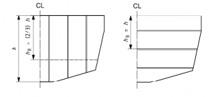
Fig 4.3 Watertight bulkheads
2. Integral tank bulkheads and boundaries ĀÅA
The design pressure
ĀÅA
on integral tank bulkheads and boundaries is:
ĀÅA G ËŊYA kNĤmË
where
YA is the water head, in metres, measured as follows (see Fig 4.4):
- for plating, the distance from a point 2/3 of overflow, whichever is the greater;
- for vertical stiffeners, the distance from a
of the depth of the panel below top of tank or top point 2/3 of the depth of the stiffener below top of
Ch 4 Structures Ch 4
![]()
tank or top of the overflow, whichever is the greater;
- for horizontal stiffeners, the height measured from the stiffener to top of tank or top of over- flow, whichever is the greater.
Where there are plates of different thicknesses or scantlings, YA for each plate panel shall be meas- ured to the lowest point of the panel.
For determination of the design pressure, the top of the overflow shall not be taken < 2 m above the top of the tank.
Where the tanks form part of the deck, this has to be assessed according to the requirements of this section.
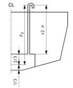
Fig 4.4 Measurement of dimensions for integral tank scantling calculation
3. Wash plates
(1) Tanks shall be subdivided as necessary by internal baffles or wash plates. Baffles or wash plates that support hull framing shall have scantlings equivalent to stiffeners located in the same position.
(2) Wash plates and wash bulkheads shall, in general, have an area of perforation not < 50 % of the total area of the bulkhead. The perforations shall be so arranged that the efficiency of the
bulkheads as a support is not impaired.
(3) The general stiffener requirement for both minimum section modulus and second moment of area may be 50 % of that required for stiffener members of integral tanks.
4. Collision bulkheads
The scantlings of collision bulkheads, where fitted, shall not be less than required for integral tank bulkheads.
5. Non-watertight or partial bulkheads
Where a bulkhead is structural but non-watertight, the scantlings shall be as required in 507.
6. Transmission of pillar loads
Bulkheads that are required to act as pillars in the way of under-deck girders subjected to con- centrated loads and other structures that carry heavy loads shall be dimensioned according to these loads.
304. Design pressures for structural components where
ÝAĄ
would be ≤ 0.25
1. The dynamic effect reduces as the structural component size increases. For very large structural components, the design pressure should be based on the hydrostatic pressure, since it is this load that can be reasonably taken as being distributed over the whole area of the component.
2. “Very large” components are defined and longer panel sides (panels) or the
as panels or stiffeners for which the product of the shorter span and spacing (stiffeners) exceeds the following areas:
- for bottom structure, 30 % of the
ÄBÄ ×ABÄ
product;
Ch 4 Structures Ch 4
![]()
- for side structure, 30 % of the ÄBÄ × Ǽ product, where Ǽ is the hull total depth;
- for deck structure, 30 % of the
ÄBÄ ×ABÄ
product.
In such cases, irrespective of the pressure loads obtained from 301. and 302., the design pressures
need not be taken greater than:
ÄǼÆ
- for bottom structure, ŊĦĖÈŶ ŊĦĖĖ , but not
< 5 kNĤmË;
- for side structure, ŊĦĖŶ
ÄǼÆ
ŊĦĖĖ , but not < 5 kNĤm Ë;
- for deck structure, 5 kNĤmË.