Iranian Classification Society Rules

< Previous | Contents | Next >
Section 4 Scantling of Plating
401. Plating - Scantling equations
1. Thickness adjustment factors for plating
(1) Bending deflection factor ÝË for sandwich plating
ÝË = 0.017
(2) Panel aspect ratio factor for strength ÝË and for stiffness ÝĖ
The panel aspect ratio factors for strength ÝË and for stiffness ÝĖ are given in Table 4.4.
Table 4.4 Values of
ÝË and ÝĖ in function of aspect ratio
ŶĤẄ for isotropic panels
Panel aspect ratio ŶĤẄ | Factor ÝË ÝË to be taken = 0.5 for laminated wood plating | Factor ÝĖ |
> 2.0 | 0.500 | 0.028 |
2.0 | 0.497 | 0.028 |
1.9 | 0.493 | 0.027 |
1.8 | 0.487 | 0.027 |
1.7 | 0.479 | 0.026 |
1.6 | 0.468 | 0.025 |
1.5 | 0.454 | 0.024 |
1.4 | 0.436 | 0.023 |
1.3 | 0.412 | 0.021 |
1.2 | 0.383 | 0.019 |
1.1 | 0.349 | 0.016 |
1.0 | 0.308 | 0.014 |
ÝË can be evaluated by the formula below, keeping 0.308 < ÝË < 0.5 | ÝĖ can be evaluated by the formula below, keeping 0.014 < ÝĖ < 0.028 | |
ŊĦËĒËFŶĤẄFËĞ ŊĦŊËŊFŶĤẄFG ŊĦÈÈĖ ÝË G JF Ĥ FŶ Ë ẄG Ħ Ŋ ĖËĖ FŶ ĤẄF Ğ ËĦĖÈË | ŊĦŊËĒFŶĤẄFË G ŊĦŊËŊFŶĤẄFĞ ŊĦŊËË ÝĖ G JF Ĥ FŶË ẄG Ħ Ë ĖÈĖ FŶ ĤẄF Ğ ËĦËŊĒ |
(3) Curvature correction factor ÝÆ for curved plates
The curvature correction factor ÝÆ is given by Table 4.5, where Ẅ is the crown of the panel,
as defined in Fig 4.5. ÝÆ shall not be taken < 0.5 nor > 1.
Ch 4 Structures Ch 4
![]()
Table 4.5 Curvature correction factor ÝÆ
ẄĤẄ | ÝÆ |
0 to 0.03 | 1.0 |
0.03 to 0.18 | ĖĦĖĖẄ ËĦË G J |
> 0.18 | 0.5 |
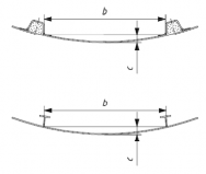
Fig 4.5 Measurement of convex curvature
(4) Shear force and bending moment on a panel
In the case
on non-homogenous or non-isotropic material, the shear force and bending moment
on panel are complying with following equations.
ÁẀ G ĬJÝ
×Ý × Ā × Ẅ × ËŊG Ė is the shear force in the middle of the Ẅ dimension in N/mm
Æ ÅĂÆ
(27)
À ĒĖ
ĖĖ × Ý
Ë × ËÝ × Ā × ẄË × ËŊG È
is the bending moment in the Ẅ direction in N/mm
Ẁ G Ħ Æ Ë
(28)
Where the panel stiffness is not similar in the two principal panel directions, see ISO 12215-5
Annex H.
402. FRP single-skin plating
1. Design stress for FRP single-skin plating
Table 4.6 Design stresses for FRP single-skin plating
Material | Structural element | Design stress ŖẀ NĤmmË |
FRP single skin | All elements | 1.5 ŖŹX |
where
ŖŹX
is the minimum ultimate flexural strength, in newtons per square millimetre.
2. Required thickness for FRP single-skin plating
The following equation is only valid if the mechanical properties in both directions differ by < 25
%; otherwise the panel shall be analysed in accordance with ISO 12215-5 Annex H. The minimum required single-skin plating thickness Ź is
Ch 4 Structures Ch 4
![]()
Ĭ
JĀ ×Ý
Ë mm (29)
Ź G Ẅ× ÝÆ × JËŊŊŊ× Ŗ
Ẁ
where
Ẅ is the short dimension of the panel in millimetres;
ÝÆ is the curvature correction factor for curved panels given in Table 4.5;
Ā is the design pressure (bottom, side, deck and superstructure, etc.) of the panel in accord- ance with Ch.3, in kilonewtons per square metre;
ÝË is the panel aspect ratio factor for bending strength given in Table 4.4;
ŖẀ is the design stress for FRP plating given in Table 4.6, in newtons per square millimetre.
For FRP, it shall be translated into a mass of dry fibre reinforcement ŽX (in kilograms per square metre) using the fibre mass content Ō according to the methods of ISO 12215-5 Annex C,
3. Use of bulking material
(1) General
A bulking material is a core material (thick fabric, resin-rich felt, syntactic foam, etc.) intended to increase the thickness of a laminate. The bulking material functions either as an element only carrying shear (like in a sandwich) or as an elemnet of the laminate working both in shear transmission and flexure.
(2) Resin-saturated foam or felt
Bulking materials having a strength > 3 NĤmmË may be substituted for the central layers of a
single-skin FRP laminate, providing the total thickness Ź of single skin determined by
(29) according to the following requirements ;
(A) if the total thickness is 1.15Ź, the bulking material thickness shall be 0.33 time
laminate thhickness, i.e. a bulking thickness 0.383Ź and each skin 0.383Ź ;
(B) if the total thickness is 1.30Ź, the bulking material thickness shall be 0.50 time laminate thhickness, i.e. a bulking thickness 0.65Ź and each skin 0.325Ź ;
For a total thickness between 1.15Ź and 1.30Ź, bulking thickness may be interpolated.
Equation
the total the total
403. Metal plating - Steel and aluminium alloy
1. Design stress for metal plating
Table 4.7 Design stresses for metal plating
Material | Structual element | Ë Design stress ŖẀ (NĤmm ) |
Aluminium alloys | All elements | Ŵ 0.6ŖŹŽ or 0.9 ŖŻŽ |
Steel | All elements | Ŵ 0.6ŖŹ or 0.9 ŖŻ |
a The lesser value applies. | ||
where for steel
: ŖŻ
- Minimum tensile yield strength, (NĤmm Ë)
for welded aluminium :
ŖŹŹ
ŖŻŽ ŖŹŹŽ
- Minimum ultimate tensile strength, (NĤmm Ë)
- Minimum tensile yield strength in the welded condition, (NĤmm Ë)
- Minimum ultimate tensile strength in the welded condition (NĤmm Ë)
For aluminium adhesively bonded or mechanically fastened, ŖŻ and
2. Required thickness for metal plating
ŖŹŹ
are in the unwelded state.
The thickness of metal required by the following does not take into account any corrosion margin or the effect of fabrication techniques. Coating is considered to be used where needed.
Ch 4 Structures Ch 4
![]()
The minimum required thickness of the plating Ź is
Ĭ
JĀ ×Ý
Ë (mm) (30)
Ź G Ẅ× ÝÆ × JËŊŊŊ× Ŗ
Ẁ
where
Ẅ : the short dimension of the panel (mm)
ÝÆ : the curvaure correction factor for curved panels given in Table 4.5.
Ā : the design pressure in accordance with Ch.3 (bottom, side, deck, etc.) (kNĤmË)
ÝË : the panel aspect ratio factor for bending strength given in Table 4.4.
ŖẀ : the design stress for metal plating given in Table 4.7.
404. Laminated wood or plywood single-skin plating
See ISO 12215-5 Annex E for Laminated wood or plywood single-skin plating.
405. FRP sandwich plating
1. General
This section applies to sandwich panels where the outer and inner skins are similar in layout, in strength and in elastic properties. The skin laminates are considered similar when the ratio of their mechanical properties is within 25 percent of each other.
If this is not the case, the sandwich shall be analysed in accordance with ISO 12215-5 Annex H. In any case, the thickness requirement from the shear load capacity of 4. shall be followed.
2. Design stress for sandwich plating
Table 4.8 Design stresses for FRP sandwich plating
Material | Structural element | Design stress Ŗ or (NĤmmË) ẀŹ ŖẀẄ |
FRP sandwich | Hull, deck, superstructures, structural and watertight bulkheads and tanks | In outer skin 0.5ŖŹŹ In inner skin 0.5Ŗ or 0.3ĖĬÁJ× Á a × Ă ŹẄ Æ ÆĀ Æ |
a See 3. and Equation (34). | ||
where
for FRP sandwich: ŖŹŹ is the minimum ultimate tensile strength of the skin, in newtons per square milli- metre;
ŖŹẄ
is the minimum ultimate compressive strength of the skin, in newtons per square
millimetre.
3. Minimum section modulus and second moment
The required minimum section modulus about the neutral axis of a strip of sandwich panel shall not be less than the values given by Equations (31) and (32).
Minimum required section modulus of the outer skin of sandwich 1 cm wide:
ẄË × ÝÆ Ë × Ā × ÝË
ÅÀŊ /1 cm width =
![]()
ẀŹŸ
JÈ× ËŊÈ ×Ŗ
outer skin cm Ė/cm
(31)
Ch 4 Structures Ch 4
![]()
Minimum required section modulus of the inner skin of sandwich 1 cm wide:
Ẅ × ÝÆ × Ā × ÝË
Ë Ë
ÅÀ /1 cm width = inner skin cm Ė/cm (32)
ẀẄY
Y JÈ× ËŊÈ ×Ŗ
Minimum required second moment (moment of inertia) for a strip of sandwich 1 cm wide:
ẄĖ × ÝÆ Ė × Ā × ÝĖ
Â/1 cm width =
Ë YŸ
JËË × ËŊÈ × Ý × Á
cm Ė/cm
(33)
where
Ẅ is the shorter dimension of the panel, but shall not be taken > 330 ÄĂ, in millimetres;
ÝÆ is the curvature correction factor for curved panels given in Table 4.5;
Ā is the pressure (bottom, side, deck, etc.) for the panel in accordance with Clause 8, in kil- onewtons per square metre;
ÝË is the panel aspect ratio factor for bending strength given in Table 4.4; ÝĖ is the panel aspect ratio factor for bending stiffness given in Table 4.4; ÝË = 0,017 is the sandwich bending deflection factor;
ÁYŸ is the mean of the inner and outer face moduli, in newtons per square millimetre (see
Annex C); this approach is suitable when the inner and outer faces are similar, i.e. differ by not > 25 %.
Design tensile stress on the outer skin:
ŖẀŹŸ
is the tensile design stress of the outer skin given in Table 4.8, i.e. 0.5 ŖŹŹ , in new- tons per square millimetre
Design compressive stress on the inner skin:
ŖẀẄY
is the compression design stress of the inner skin which is the lesser of
0.5 ŖŹẄ or ŊĦĖĬJÁẄ
×ÁẄŸ
×ĂẄ (34)
Ė
where
ÁÆ is the compressive Á modulus of inner skin in 0°/90° in-plane axis of panel (see ISO 12215-5 Annex C), in newtons per square millimetre,
ÁÆĀ is the compressive Á modulus of core, perpendicular D), in newtons per square millimetre;
ĂÆ is the core shear modulus in the direction parallel to in newtons per square millimetre.
to skins (see ISO 12215-5 Annex load (see ISO 12215-5 Annex D),
Equation (33) may also be written as
ẄĖ ×Ý Ė ×Ā×Ý
ÁÂ per mm width =
J
Ẅ Ė NĤmmË /mm
ËË × ËŊĖ × Ý
(35)
Ë
4. Thickness required by shear load capabilities
![]()
In order to transmit the shear load, the effective thickness of sandwich laminate than given by Equation (36):
ŹZ shall not be less
Ch 4 Structures Ch 4
![]()
ŹZ ≥ ĬJÝ
ÝÅĂÆ ×Ā× Ẅ
Æ JËŊŊŊ×Ŗ
mm (36)
Ẁ
where
ŹZ G ŹẄ Ğ ŊĦÈFŹY Ğ ŹŸ F is the distance between mid-thickness of the skins of the sandwich, in milli- metres;
ÝÆ ŹŸ ŹY
ŹẄ ÝÅĂÆ
is the curvature correction factor defined in Table 4.5;
is the thickness of the sandwich outer skin, excluding gel coat, in millimetres; is the thickness of the sandwich inner skin, in millimetres;
is the thickness of the core, in millimetres;
is the shear strength aspect ratio factor, given in Table 4.10;
Where the elastic properties of the skins are different by > 25 % in the principal axes, shall not be taken < 0.465;
ÝÅĂÆ
Ā is the pressure (bottom, side, deck, etc.) for the panel in accordance with Ch. 3, in kilo-
newtons per square metre;
Ẅ is the short dimension of the panel in millimetres;
ŖẀ is the design shear stress of the core, according to Table 4.9, in newtons millimetre.
per square
Table 4.9 Design shear strength of sandwich cores
Material | Core design shear stress Ŗ (NĤmm Ë ) Ẁ |
End grain balsa | 0.5 ŖŹ |
Core having shear elongation at break < 35 % (cross-linked PVC, etc.) | 0.55 ŖŹ |
Core having shear elongation at break > 35 % (linear PVC, SAN, etc.) | 0.65 ŖŹ |
Honeycomb cores (to be compatible with marine application) | 0.5 ŖŹ |
ŖŹ is the minimum ultimate core shear strength, in newtons per square millimetre.
Table 4.10 Shear strength aspect ratio factor ÝÅĂÆ
ŶĤẄ | > 4.0 | 3.0 | 2.0 | 1.9 | 1.8 | 1.7 | 1.6 | 1.5 | 1.4 | 1.3 | 1.2 | 1.1 | 1.0 |
Ý a ÅĂÆ | 0.500 | 0.493 | 0.463 | 0.459 | 0.453 | 0.445 | 0.435 | 0.424 | 0.410 | 0.395 | 0.378 | 0.360 | 0.339 |
Ë a The values of Ý may be calculated by the equation Ý G ŊĦŊĖÈ ĞŊĦĖŊĖ × Ŷ GŊĦŊŊ× Ŷ for ŶĤẄ Ĥ Ë ÅĂÆ ÅĂÆ FJẄ F FJẄ F | |||||||||||||
5. Minimum core shear strength
![]()
For bottom laminate, the value of the design shear strength of the core, as used in 4, shall be at least in accordance with to Table 4.11.
Ch 4 Structures Ch 4
![]()
Table 4.11 Minimum design core shear according to craft length
ÄĂ (m) | < 10 | 10 to 15 | 15 to 24 |
Ŗ min (NĤmm Ë) Ẁ | 0.25 | 0.25 + 0.03(ÄĂ -10) | 0.40 |
6. Minimum sandwich skin fibre mass requirements
In order to reduce the risk of skin puncture or grams per square metre is given by
damage, the required minimal fibre mass in kilo-
Ë
ŽŸZ G ÝǼÆ × ÝĖ × ÝÈ × ÝÈ × FŊĦËÄBÄ Ğ ŊĦËÈF kgĤm (37)
ŽYZ G
ŊĦĒ× ŽŸZ
kgĤm Ë
(38)
where ŽŸZ ŽYZ
ÝĖ
ÝÈ
ÝÈ
is the fibre mass per square metre of the outer skin, in kilograms per square metre; is the fibre mass per square metre of the inner skin, in kilograms per square metre; is the sandwich minimum skin location factor where
ÝĖ = 1 for hull bottom, ÝĖ = 0.9 for side shell, ÝĖ = 0.7 for deck,
is the sandwich minimum skin fibre type factor where
ÝÈ = 1.0 for E-glass reinforcement containing up to 50 % of chopped strand mat by mass,
ÝÈ = 0.9 for continuous glass reinforcement (i.e. bi-axials, woven roving, unidirectionals, double bias or multiaxial),
ÝÈ = 0.7 for continuous reinforcement using aramid or carbon or hybrids thereof, is the sandwich minimum skin care factor where
ÝÈ = 0.9 for craft where the sandwich outer skin is expected to be punctured after hitting a sharp object;
ÝÈ = 1 for other craft.
If ÝÈ = 0.9, a statement warning that the craft may be punctured after hitting a sharp object and that this damage shall be quickly repaired shall be inserted in the owner's manual.
406. Single-skin plating minimum thickness
1. Minimum thickness or mass of reinforcement for the hull
For metal or plywood
ÀÂÀ G È Ē Ē ÄǼÆ
Ź Ý × FA Ğ Ý × Ã Ğ Ý × Ŷ ŊĦĖĖF
mm (39)
For FRP, minimal dry fibre weight Ž
G ŊĦĖĖ × Ý × FA ĞÝ × Ã ĞÝ × Ŷ
ŊĦĖĖ F
kgĤm Ë
(40)
ÀÂÀ
È Ē Ē
ÄǼÆ
where
![]()
A, ÝÈ, ÝĒ and ÝĒ are defined in Table 4.12. For sailing craft à shall be taken as ËĦĖÈĬJÄBÄ .
Ch 4 Structures Ch 4
![]()
Table 4.12 Minimum thickness factors
Material | Position | A | ÝÈ | ÝĒ | ÝĒ |
FRP | Bottom | 1.5 | As defined in 405. 6. | 0.03 | 0.15 |
Side/transom | 1.5 | 0 | 0.15 | ||
Aluminium | Bottom | 1.0 | ĬJËËÈĤŖŻ | 0.02 | 0.1 |
Side/transom | 1.0 | 0 | 0.1 | ||
Steel | Bottom | 1.0 | ĬJËĖŊĤŖŻ | 0.015 | 0.08 |
Side/transom | 1.0 | 0 | 0.08 | ||
Plywood | Bottom | 3.0 | ĬJĖŊĤŖ ŹX | 0.05 | 0.3 |
Side/transom | 3.0 | 0 | 0.3 |
2. Minimum deck thickness
The values of minimum deck thickness shall be derived from Table 4.13.
Table 4.13 Minimum deck thickness
Location | Deck minimum required thickness ŹÀÂÀ mm | |||
FRP | Aluminium | Steel | Wood, plywood | |
Deck | ÝÈ FËĦĖÈ Ğ ŊĦËĖÄBÄ F | ËĦĖÈ Ğ ŊĦŊÈÄBÄ | ËĦÈĞŊĦŊĒÄBÄ | ĖĦĒĞŊĦËĒÄBÄ |