Iranian Classification Society Rules

< Previous | Contents | Next >
Section 5 Requirements for Stiffening
501. Stiffening members requirements
1. General
Plating shall be supported by an arrangement of stiffening members. The relative stiffness of pri- mary and secondary stiffening members shall be such that loads are effectively transferred from secondary to primary, then to shell and bulkheads.
502. Properties adjustment factors for stiffeners
1. Curvature factor for stiffeners ÝÆÅ
The curvature factor
ÝÆÅ shall be taken as listed in Table 4.14.
![]()
Table 4.14 Values of curvature factor for stiffeners ÝÆÅ
ẄŹ JŶŹ | ÝÆÅ |
0 to 0.03 | 1 |
0.03 to 0.18 | 1.1-3.33(ẄŹĤŶŹ ) |
> 0.18 | 0.5 |
Ch 4 Structures Ch 4
![]()
where
ẄŹ is the crown of a curved stiffener, in millimetres;
ÝÆÅ
applies to convex or concave stiffeners; it shall not be taken < 0.5 nor > 1.
2. Stiffener shear area factor ÝÅA
The stiffener shear area factor
ÝÅA
shall be taken as listed in Table 4.15.
Table 4.15 Values of shear area factor ÝÅA
Stiffener arrangements | ÝÅA |
Attached to the plating | 5 |
Other arrangements (floating) | 7.5 |
503. Design stresses for stiffeners
Table 4.16 Design stresses for stiffeners
Material | Tensile and compressive design stress ŖẀ NĤmmË | Design shear stress ŖẀ NĤmmË |
FRP | 0.5 Ŗ and 0.5 Ŗ a ŹŹ ŹẄ | 0.5 ŖŹ |
Aluminium alloys | 1.7 Ŗ b ŻŽ | b 0.4 ŖŻŽ |
Steel | 1.8 ŖŻ | 0.45 ŖŻ |
Laminated wooden frames | 0.45 Ŗ c ŹX | 0.45 ŖŹ |
Solid stock wooden frames | 0.4 Ŗ c ŹX | 0.4 ŖŹ |
Plywood on edge frames | 0.45 Ŗ c ŹX | 0.45 ŖŹ |
NOTE These design stresses also apply for the attached plating of the stiffener, according to its material. | ||
a Ŗ is considered where stressed in compression (usually the stiffener top flange) and Ŗ is con- Ẅ Ź sidered where stressed in tension (usually the plating); both verifications need to be calculated. b For welded stiffeners. If aluminium stiffeners are not welded, i.e. riveted, glued, etc., the non-welded properties shall be used. c Ŗ for laminated wooded stiffeners and Ŗ for solid stock shall be taken from ISO 12215-5 ŹX ŹX Table E.1. For plywood, ŖŹX shall not be taken from Table E.2 but from Tables E.3 or E.6. | ||
ŖŹ is the minimum ultimate in-plane shear strength of the stiffener material, in newtons per square millimetre.
504. Requirements for stiffeners made with similar materials
1. For any material: minimum section modulus and shear area
The web area AB and minimum section plating of the stiffening members, shall
(42) :
modulus ÅÀ of stiffening members, including the effective be not less than the values given by Equations (41) and
ÝÅA × Ā ×Z × ŶŹ ËŊG È
cm Ë (41)
![]()
AB G JŖ Ẁ
Ch 4 Structures Ch 4
![]()
ĒĖĦĖĖ × ÝÆÅ × Ā ×Z × ŶŹ
Ë
ËŊG Ŋ
cm Ė (42)
ÅÀ G J Ẁ
where ÝÆÅ ÝÅA
Ā
Z ŶŹ ŖẀ
AB
ŖẀ
is the curvature factor for stiffeners given in Table 4.14; is the stiffener shear area factor given in Table 4.15;
is the pressure (bottom, side, deck and superstructure, etc.) for the panel, in kilonewtons per square metre;
is the spacing of stiffeners, in millimetres; is the length of the stiffener, in millimetres;
is the design stress for stiffeners given in Table 4.16, in newtons per square millimetre; is the shear area (cross-sectional area of stiffener shear web), in square centimetres;
is the design shear stress of the shear web as defined in Table 4.16, in newtons per square millimetre.
2. Supplementary stiffness requirements for FRP
For FRP stiffeners, the second moment of than given by the following formula.
area, including the effective plating, shall not be less
ÆÅ Ź
ËÈ × Ý ËĦÈ × Ā × Z × Ŷ Ė
ËŊG ËË
cm Ė (43)
 G JÝ
ËÅ × ÁŹẄ
where
ÁŹẄ is the mean of compressive/tensile in newtons per square millimetre;
modulus of the material (see ISO 12215-5 Annex C),
ÝËÅ = 0.05 is the deflection factor for stiffeners (allowable relative deflection ŻĤŶŹ ).
505. Requirements for stiffeners made with dissimilar materials
In case that dissimilar materials which mechanical properties differ by > 25 % from each other are used, see ISO 12215-5 11.5.
506. Effective plating
The lower flange of stiffening members working in bending is a band of plating called “effective plating” as shown in Fig 4.6. The effective extent of plating be shall be calculated according to Table 4.17, but shall not be taken greater than the actual stiffener spacing.
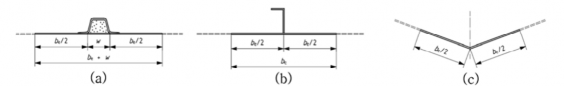
Fig 4.6 Sketch showing the effective extent of plating around a stiffener (top hat, L and chine)
Ch 4 Structures Ch 4
![]()
Table 4.17 Values of ẄẀ
Material | Steel | Aluminium | FRP single skin | FRP sandwich | Wood, plywood | |||||||
ẄẀ | 80 Ź | 60 Ź | 20 Ź | 20FŹ Ğ Ź F a | 15 Ź | |||||||
a | The attached plating is 20 ineffective, i.e ÁẄŸZẀ G Ŋ . | times | both | inner | and | outer | skins, | separated | by the core, | which | is | considered |
Where the stiffener has a significant width it may be added to be [see Fig 4.6 a)]. The above equations are valid for any stiffener: stringer, frame, bulkhead, etc.
For stiffeners along an opening, the effective extent shall be taken as 50 % of the extent as given
above.
507. Structural bulkheads
1. Plywood bulkheads
The thickness of unstiffened solid plywood bulkheads shall be not less than
ŹẄG ĒĦŊǼẄ mm (44)
where
ǼẄ is the depth of the bulkhead from bottom of canoe body to deck at side, in
2. Sandwich bulkheads
(1) Core
In addition to the requirements of (2) and (3)
- the core shear strength shall be in accordance with to 405. 5. and Table 4.11,
- the core thickness shall be at least five times the thickness of the thinnest skin.
(2) Sandwich bulkheads with identical plywood skins
metres.
The thickness of skins
ŹZ and of core ŹẄ shall be such that
Ë Ë Ė
ŹẄ
ŹZ × ŹẄ ≥ J
mmË and
ŹẄ
ŹZ × J
Ẅ
Ź
≥ JËË
mmĖ (45)
where
ŹẄ
ŹZ and ŹẄ
is the solid plywood bulkhead thickness defined by Equation (54); are as defined in 405. 4.
(3) Sandwich bulkheads with identical FRP skins
The thickness of skins ts and of core tc shall be such that
Ë Ë Ė
ŹẄ
ŹZ × ŹẄ ≥ J
where
FËJŖÈẀF
mm and
ŹẄ
ŹZ × J
≥ ŹẄ
JËË FJÁĖŊŊYŊŸ F
mm (46)
ŹẄ is the solid plywood bulkhead thickness
3. Metal bulkheads
They shall be calculated as watertight bulkheads.
Ch 4 Structures Ch 4
![]()