Iranian Classification Society Rules

< Previous | Contents | Next >
Section 6 Structural Arrangement
601. Stiffening
1. General
(1) The hull, deck and deckhouse plating shall be stiffened as necessary, by any combination of longitudinal and transverse conventional stiffeners, structural bulkheads, internal furniture such as berths and shelves, and internal tray mouldings, providing these may be considered as “load bearing”. The arrangement is usually made with stiffeners supported by deeper and stronger stiffeners, crossing perpendicularly.
(2) Fig 4.7, 4.8 and 4.9 illustrate characteristic arrangements that comply with good practice. These figures apply to both sailing and non-sailing craft, and combinations of arrangement within a single craft are acceptable. Small crafts (generally those of hull length less than about 9 m in length) employ natural stiffeners such as deck edge, round bilges, hard chines, keel, etc. to de- fine panels and then need no further stiffening.
(3) Equivalence criteria
Other arrangements are possible, but these shall follow good practice principles (as illustrated by
Fig 4.7, 4.8 and 4.9) of effective and smooth transmission of stresses due to pressure loads and concentrated loads (mast, keel, rudder, etc) from the load point into the supporting structure (see 603. and 604.).
(4) Longitudinally framed craft
In the example in Fig 4.7, the hull shell is stiffened by longitudinal secondary stiffeners sup- ported by transverse primary stiffeners, such as web frames, bulkheads and deep floors. The ex- ample given is typical for an FRP craft.
(5) Transversally framed craft
In the example in Fig 4.8, the hull shell is stiffened by transverse frames (secondary stiffeners)
that are typically supported at the centreline, at the chines or turn of bilge and at deck level. In larger crafts, girders (primary stiffeners) may be fitted, which support these frames and also assist in carrying hull girder loads.
(6) Small, slow craft stiffened by keel, gunwale stringer, structural sole and thwarts
It is common for small craft (i.e. those of hull length less than 6 m) to have no specific stiffeners. However, components not primarily intended to be stiffeners, such as internal parti-
tions may act
as such. These components may need to be reinforced for this other role as
“stiffeners”. In Fig 4.9, the thwarts, front and aft locker, cockpit sole and gunwale are used in this way.
(7) Load bearing elements
To be considered as “load bearing”, the supporting member shall be effectively attached to the plating by any combination of welding (continuous or intermittent), bonding with structural qual- ity adhesive (e.g. use of epoxy fillets) or fibre reinforced bonding angles or other methods ap- propriate to the materials. In addition, the member in question shall be constructed of material acceptable for hull construction in accordance with Ch 4, and shall be able to carry the forces and moments associated with the effective support assumption as defined there.
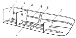
1 transom
4 side longitudinal stiffener (stringer)
7 bottom longitudinal stiffener (girder or stringer)
2 gunwale stringer
5 web frame
3 bulkhead
6 deep floor
NOTE 1, 3, 5 and 6 are primary stiffeners; 2, 4 and 7 are secondary stiffeners.
Fig 4.7 Longitudinally framed small craft
Ch 4 Structures Ch 4
![]()
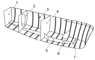
1 transom
4 bulkhead
7 deep floor
2 bulkhead
5 bottom girder
3 frame
6 deep floor
Fig 4.8 Transversally framed small craft
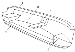
1 gunwale stringer
4 thwarts
2 keel
5 deep floor
3 structural sole
Fig 4.9 Small, slow craft stiffened by keel, gunwale stringer, structural sole and thwarts
602. Hull girder strength
This section is based on the assumption that hull and deck scantlings are governed by local loads, which is usually the case for craft of normal proportions and is especially so for longitudinally framed craft.
For the following craft, an explicit longitudinal strength and buckling assessment is recommended:
- transversely framed non-sailing craft where
Ãmax
JĬJÄ BÄ
IÈ;
- transversely framed sailing crafts experiencing large rig loads;
- craft with large deck openings or craft with
ÄĂ
JǼmax
IËË
603. Load transfer
1. General
The structural geometry shall be so arranged and detailed as to ensure a smooth transfer of loads throughout the structure. Concentrated loads (e.g. mast step for a keel stepped mast, mast pillar for a deck stepped mast) shall be transmitted into the surrounding structure by a series of stiff support-
Ch 4 Structures Ch 4
![]()
ing members. In no case shall concentrated load points be landed on unsupported plating. In gen- eral, concentrated loads shall be introduced into the adjacent structural elements by shear load car- rying brackets, flanges or floors. Knife edge load crossing shall be avoided (see 5).
2 gives examples of good practice load transfer arrangements. Other arrangements need to be spe- cifically engineered.
2. Examples of good practice load transfer arrangements
The list below gives examples of good practice load transfer arrangements.
(1) Stiffeners (generally angle bar, tee section, top hats or flat bars, etc.) and girders (including en- gine girders) do not terminate abruptly, but are suitably terminated to develop their bending strength and shear strength at the supporting member, with brackets or without brackets, but with structurally effective attachment of web and flange to the supporting member (see Fig 4.10). Where stiffeners are lightly loaded, they may have tapered (sniped) ends, provided the slope of the taper is at least 30 % and that the plating between the end of the stiffener and the supporting structure is designed or able to transmit the shear force and bending moment of the tapered stiffener [see Fig 4.10 c)].
(2) Floors smoothly taper in depth towards that of the attached transverse frame. Where no trans- verse frames are fitted, the floor is attached to the side shell over a sufficient length to ensure that the shear force (due to keel moment or bottom pressure) can be adequately transferred to the side shell (see Fig 4.11).
(3) Cut-outs and sharp corners are avoided in load-carrying structures such as shell, deck, primary and secondary stiffening members. Where cut-outs cannot be avoided, the depth of any cut-out does not exceed 50 % of the depth of the web of the member, and the length of the cut-out does not exceed 75 % of the depth of the web of the member, unless effectively engineered. Cut-outs shall have radius corners not less than 12 % of the cut-out depth or 30 mm, whichever is the greater. Cut-outs are avoided within 20 % of the span from the support points and by way of concentrated loads on the member.
3. Openings in deck and shell according to good practise
Openings in decks and shell have radius corners not less than 12 % of the width of opening, but
need not exceed 300 mm and are not less than 50 mm. This does not apply where reinforced by a structural flat bar or equivalent (see Fig 4.12).
the edges are
It is also good practice to minimize sharp cut-outs in structurally loaded panels and stiffeners, un- less accordingly reinforced.
a) Stiffener ending in panel, poor practice and good practice solution
b) Bracket, poor practice and good practice solution
Ch 4 Structures Ch 4
![]()
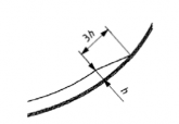
c) Tapered ends acceptable provided the vertical load can be taken by the shell
1 risk of crack
Y height of stiffener
Fig 4.10 Detail of stringer and bracket end
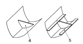
4. Floating frame systems
Floating frame systems (see eners) effectively sits on top
Fig 4.13) are those where one set of stiffeners (the “floated” stiff- of another set without being directly attached to the hull plating. Only
the second set (the “attached” stiffener) is directly attached to the plating. When analysing such
floating frames, the effective plating of the floating frame is to be taken as zero.
For all materials, particular metal crafts or wooden crafts that use plywood frames, these “floating” frames are normally I beams “attached” to a T, L or U stringer. Attention shall be given to the strength of the weld or glued area between the “floating” frame and stringer, torsional (tripping) or shear buckling of the stringer and the frame transverse web and knife edge load crossing (see 5.), which requires explicit calculation. By way of Guidance, the weld or glue area shall generally not be less than the stiffener web area, AB, Equation (41).
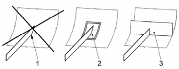
a) Stiffener ending in shell, poor practice and good practice
b) Deep floor/partial bulkhead
1 hard spot, risk of crack, poor practice
2 reinforced plating, acceptable practice
3 transverse floor or bulkhead, good practice
4 no longitudinal structure at top end of deep floor, acceptable practice
5 cabin sole, deck or longitudinal stiffener on top of floor, good practice
Fig 4.11 Detail of stiffener ending on the plating
Ch 4 Structures Ch 4
![]()
Dimensions in millimetres

Ą radius corner
B width of opening
Fig 4.12 Deck and shell openings corner radius
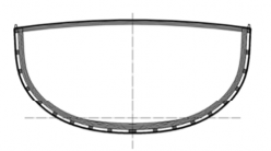
Fig 4.13 Section of a wooden craft with floating frame
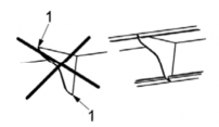
5. Knife edge load crossing
Knife edge load crossing happens when two load carrying members cross at a right angle. This shall be avoided as there is a high stress concentration at the point of connection of the two members. In the case of knife edge load crossing, at least one of the members shall be reinforced as shown in Fig 4.14.
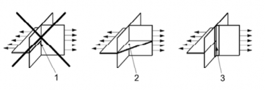
1 stress concentration (knife edge load crossing), poor practice
2 bracket transferring the load from the horizontal plate to the vertical plate, good practice
3 reinforcement with an L shaped stiffener or tabbing (for use in lightly loaded areas only), acceptable practice
Fig 4.14 Knife edge load crossing
6. Equivalent criteria
Other arrangements are possible but these shall follow good practice principles (as illustrated by Fig 4.10 to 4.14) of effective and smooth transmission of stresses, generous radii, use of connect- ing brackets, gentle tapering of material, avoidance of stress concentration features and careful placement of any lightening holes.
Ch 4 Structures Ch 4
![]()
604. Determination of stiffener spans
1. General
In order to establish whether a stiffener complies with the requirements of the Ch.6 series, the spacing and span of the stiffener being considered shall be established.
The spacing is the distance between successive stiffeners, measured perpendicular to the stiffener axis. The span is the distance between support points. It is important to appreciate that span ex- ercises a very strong influence on the bending strength and deflection of any stiffener.
In order to simplify the calculations, this chapter considers stiffeners as isolated beams under a uni- formly distributed pressure load. ISO 12215-5 provides Guidance on locating support points for isolated stiffeners.
In reality, small craft structures often comprise a set of transverse stiffeners that intersect a set of longitudinal stiffeners. This may be termed a “grid”. Each point where a transverse member crosses a longitudinal member is termed an “intersection point”.
In some cases, it is correct to take the stiffener span as the distance between adjacent intersection points, but in other cases this is too optimistic. The support which one set of crossing members of- fers to the other set is a complex function of the relative flexural rigidity (ÁÂ) and the grid di- mensions between well defined supports such as bulkheads, side shell, partitions and other very deep members. This subclause provides procedures for determination of stiffener spans.
2. Deep stiffeners crossing shallow stiffeners
Where one set of members have a depth of at least twice that of the other set, these deeper stiff- eners are called “primary members” and the shallower stiffeners are called “secondary members”.
The span of primary members, ŶŹ , is the grid dimension in the direction of the primary member. The span of secondary members, ŶŹ , is the spacing of the primary member.
3. Stiffeners crossing similar depth stiffeners
(1) General
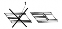
This arrangement is commonly found in small craft as a tray moulding (see Fig 4.15) and is often referred to as “egg-box” style. Neither set of members can be categorized as primary or secondary as the degree to which one set supports the other is indeterminate by simple means of assessment.
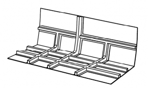
Fig 4.15 “Egg-box” style tray mouldings
In such cases, the procedure described in (2) and (3) shall be adopted.
(2) Stiffeners running in the shorter of the grid dimensions
The span used to determine the design bending moment and shear force shall be taken as 60 % of the grid dimension.
The design pressure shall be obtained using a design area, AǼ, based on the stiffener spacing and 60 % of the grid dimension.
(3) Stiffeners running in the longer of the grid dimensions
Ch 4 Structures Ch 4
![]()
The span
to be used to determine the design bending moment and shear force shall be taken as
150 % of the distance between intersection points.
The design pressure shall be obtained using a design area, AǼ, based on the stiffener spacing and 150 % of the distance between intersection points.
605. Detail of structures
The items which is not mentioned in this chapter are to be in accordance with ISO 12215-6. ![]()
Ch 5 Stability and buoyancy Ch 5
![]()