Iranian Classification Society Rules

< Previous | Contents | Next >
Section 2 Non-sailing Crafts of Hull Length Greater than or Equal to 6 m
201. Tests to be applied
Non-sailing crafts of hull length greater than or equal to 6 m shall comply with all the require- ments of anyone of six options according to amount of flotation and decking, and whether the craft
is fitted with suitable recesses. given in Table 5.1.
These options and the tests to be applied (as described in 202.) are
Table 5.1 Tests to be applied
Option | 1 | 2 | 3 | 4 | 5 | 6 |
Categories possible | A and B | C and D | B | C and D | C and D | C and D |
Decking or covering | Fully decked | Fully decked | Any amount | Any amount | Partially decked | Any amount |
Downflooding openings | 202. 1 (1) | 202. 1 (1) | 202. 1 (1) | 202. 1 (1) | 202. 1 (1) | 202. 1 (1) |
Downflooding-height test | 202. 1 (2) | 202. 1 (2) | 202. 1 (2) | 202. 1 (2)(1) | 202. 1 (2) | 202. 1 (2) |
Offset-load test | 202. 2 | 202. 2 | 202. 2 | 202. 2 | 202. 2 | 202. 2 |
Resistance to waves + wind | 202. 3 | 202. 3 | ||||
Heel due to wind action | 202. 4(2) | 202. 4(2) | 202. 4(2) | 202. 4(2) | ||
Flotation requirements | 202. 5 | 202. 5 | ||||
Flotation material | Annex F(3) | Annex F(3) | ||||
(NOTES) (1) This test is not required for crafts assessed using option 4 if, during the swamped load test in normative KS V ISO 12217-1 Annex E, the craft has been shown to support an equivalent dry mass of 133 % of the maximum total load. (2) The application of 202. 4 is only required for crafts where A ≥ Ä A . ÄÃ Ă Ă (3) See KS V ISO 12217-1 Annex F. | ||||||
202. Requirements of non-sailing
1. Downflooding
(1) Downflooding openings
crafts of hull length greater than or equal to 6 m
(A) The requirements given as follows shall apply to all downflooding openings except:
(a) watertight recesses with a combined volume less than ÄĂAĂÁÀĤĖŊ, or quick-draining recesses;
(b) piped drains from quick-draining recesses or from watertight recesses which, if filled, would not lead to downflooding or capsize when the craft is upright;
(c)
non-opening appliances;
(d) opening appliances located in the topsides which comply with KS V ISO 12216 to tightness degree 2 and which are referenced in the Owner's Manual (see normative KS V ISO 12217-1 Annex G) and are clearly marked "WATERTIGHT CLOSURE - KEEP SHUT WHEN UNDER WAY"; and which are
(i) emergency escape hatches or appliances fitted with screwed closures, or
(ii) in a compartment of such restricted volume that, even if flooded, the craft satisfies all the requirements, or
(iii)in a craft of design category C or D and which, when at loaded displacement mass, would not sink if the affected compartment was flooded as a result of the appliance being left open;
(e)
![]()
(f)
opening appliances located inboard of the topsides which comply with KS V ISO 12216 to tightness degree 2 and which are referenced in the Owner's Manual and are clearly marked "WATERTIGHT CLOSURE - KEEP SHUT WHEN UNDER WAY";
engine exhausts or other openings that are only connected to watertight systems;
Ch 5 Stability and buoyancy Ch 5
![]()
(g) openings in the sides of outboard engine wells which are of
(i) watertightness degree 2 and having the lowest point of downflooding more than 0.1 m above the loaded waterline, or
(ii) watertightness degree 3 and having the lowest point of downflooding more than 0.2 m above the loaded waterline and also above the top of the transom in way of the
engine mounting, provided that well drain holes are fitted, see Fig 5.1, or
(iii) watertightness degree 4 and having the lowest point of downflooding more than 0.2 m above the loaded waterline and also above the top of the transom in way of the engine mounting, provided that well drain holes are fitted, and that the part of the
interior or
non-quick-draining spaces into which water may be admitted has a
length less than ÄĂĤÈ and from which water up to 0,2 m above the loaded water line cannot drain into other parts of the interior or non-quick-draining spaces of the craft, see Fig 5.1.
(B) All closing appliances fitted to downflooding openings shall comply with KS V ISO 12216, according to design category and appliance location area.
(C) No opening type appliances shall be fitted in the hull less than 0.2 m above the loaded waterline unless they comply with KS V ISO 9093 or they are emergency escape hatches
complying with KS V ISO 9094.
(D) Openings within the craft, such as outboard engine trunks or free-flooding fish bait tanks, shall be considered as possible downflooding openings.
(E) For crafts to be given design category A or S, downflooding openings not fitted with any form of closing appliance shall only be permitted if they are essential for ventilation or en- gine combustion requirements.
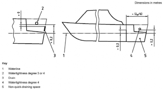
Fig 5.1 Openings in outboard engine wells
(2) Downflooding height
(A) Test
This test is to demonstrate sufficient margins of freeboard for the craft in the loaded placement condition before water is shipped aboard.
dis-
This test shall be performed using people as described below, using test weights to represent
people (at 75 kg per person), or by calculation (using a lines plan and displacement derived by a weighing or measured freeboards).
(a) Select a number of people equal to the crew limit, having an average mass of not less than 75 kg.
(b) In calm water, load the craft with all items of maximum total load, with the people
![]()
positioned so as to achieve the design trim.
Ch 5 Stability and buoyancy Ch 5
![]()
(c) Measure the height from the waterline to the points at which water could first begin to enter any downflooding opening described in 202. 1 (1) (A). Where a downflooding opening is fully protected by a higher coaming around the recess from which it leads, the downflooding height shall be measured to the lowest point of water ingress of that coaming (see KS V ISO 12217-1 Annex C).
(B) Requirements
(a) Determine the design category by comparing the measurements with the requirements for minimum downflooding height, as modified by (b) to (d) below, using either
(i) the method of normative KS V ISO 12217-1 Annex A, which generally gives the
lowest requirement, or
(ii) Figs 5.2 and 5.3 which are based only on craft length.
(b)
(c)
For crafts assessed using option 3, 4 or 6 (see Table 5.1), the required downflooding
height within ÄĂĤĖ of the bow shall be increased as shown in Fig 5.4.
crafts assessed using option 3 or 4 are permitted a 20 % reduction in required down-
flooding height in way of an outboard engine mounting position, provided that the width
of the area where this reduction applies is minimized.
(d) crafts assessed using Fig 5.2 or 5.3 shall be permitted downflooding openings having a combined clear area, in square millimetres (mmË), of not more than 50 ÄĂ Ë within the
aft quarter of ÄĂ, provided that the downflooding height to these openings is than 75 % of that required by these figures.
not less
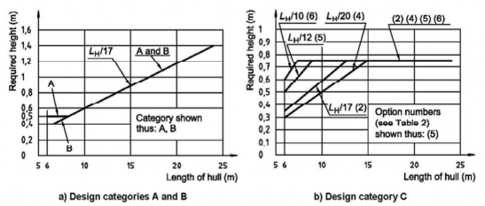
Fig 5.2 Required downflooding height - Design categories A, Band C
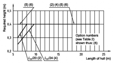
Fig 5.3 Required downflooding height - Design category D
Ch 5 Stability and buoyancy Ch 5
![]()
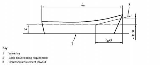
Fig 5.4 Increase in required downflooding height - Options 3, 4 and 6
2. Offset-load test
This test is to demonstrate sufficient stability for the craft against offset loading by the crew. The offset-load test shall be conducted in accordance with KS V ISO 12217-1 Annex B. During the test, the heel angle SĀ shall be not greater than
FËĖGÄĂFĖ
SĀFĄF G ËËĦÈĞJ
(see Table 5.2)
Table 5.2 Maximum permitted heel angle for offset-load test
ÄĂ (m) | 6.0 | 7.0 | 8.0 | 9.0 | 10.0 | 12.0 | 15.0 | 18.0 | 21.0 | 24.0 |
SĀFĄF (°) | 22.7 | 20.9 | 19.4 | 18.0 | 16.8 | 14.8 | 12.9 | 11.9 | 11.6 | 11.5 |
During the test, the freeboard margin to downflooding shall not be less than that given in Table 5.3
Table 5.3 Required minimum heeled freeboard margin during offset-load test
(Dimensions in metres)
Design category | A | B | C | D |
Option 1 or 3 in Table 5.1 | 0.26 AĂ | 0.145 AĂ | not applicable | not applicable |
Option 2 in Table 5.1 | not applicable | not applicable | 0.046 AĂ | 0.010 |
Option 4 in Table 5.1 | not applicable | not applicable | 0.046 AĂ | 0.010 |
Option 5 or 6 in Table 5.1 | not applicable | not applicable | 0.110 ĬJÄĂ | 0.070ĬJÄ Ă |
3. Resistance to waves and wind (design categories A and B only)
(1) General
Crafts shall be assessed using (2) and (3).
Crafts shall be assessed in the minimum operating condition unless the ratio ŶÄǼÆĤŶÀĀÆ I ËĦËÈ, in which case the loaded displacement condition shall also be assessed.
![]()
Recesses of crafts to be assigned design category A or B using comply with the plan area limitations given below, unless specific
option 1 of Table 5.1 shall account is taken of the mass
Ch 5 Stability and buoyancy Ch 5
![]()
and free-surface effect of water that recesses may characteristics.
contain when calculating the stability
If this special calculation option is used, righting moments shall be calculated assuming that
each recess is treated as though it had no drainage and is assumed to initially hold water to the following percentage of its maximum (upright) capacity:
Percentage full = ÈŊ G ËĖŊÁĤÄĂ
where Á is the minimum freeboard to the coaming of the recess in question.
Such water shall be assumed to spill out as the craft heels, the righting moments being as-
sumed to be symmetrical about the
For design category A: For design category B:
(2) Rolling in beam waves and wind The curve of righting moments of or the angle of vanishing stability Annex D.
upright.
plan area of all recesses (mË ) < ŊĦË ÄĂ AĂ
plan area of all recesses forward of ÄĂĤË (mË) < ŊĦË ÄĂ AĂ
plan area of all recesses (mË) < ŊĦĖ ÄĂ AĂ
plan area of all recesses forward of ÄĂĤË (mË ) < ŊĦËÈ ÄĂ AĂ
the craft shall be established up to the downflooding angle or 50°, whichever is the least, using KS V ISO 12217-1
The heeling moment due to wind, ÀB expressed in newton metres, is assumed to be constant at all angles of heel and shall be calculated as follows:
Ë
AÄÃ
ÀB G ŊĦĖAÄÃF JÄ Ä ĞÅÀFŽB
B
where
ÅÀ is the draught at the mid-point of the waterline length, expressed in metres;
ŽB = 28 m/s for design category A, and 21 m/s for design category B;
AÄÃ
is the windage area as defined in 102. 1, but shall not be taken as less than
ŊĦÈÈÄĂ AĂ.
Alternatively, the heeling characteristics due to wind can be assessed from wind tunnel tests. The assumed roll angle SĄ shall be calculated as follows:
SĄ G ËÈ Ğ ËŊĤÃǼ for design category A, and ËŊ Ğ ËŊĤÃǼ for design category B.
The righting moment curve and the wind heeling moment shall be plotted on the same graph as shown in Fig 5.5.
Area AË shall be greater than area AË, where AË and AË are the areas indicated in Fig 5.5.
(3) Resistance to waves
In addition to the requirements of (2), the curve of righting levers at angles of heel up to SǼ, SÃ or 50° whichever is the least, shall comply with the following.
(A) Where the maximum righting moment occurs at a heel angle of 30° or more, the righting
moment at 30° heel shall be not less than 25 kN·m for design category A, and 7 kN·m for
design category B. In addition, the righting lever at 30° shall be not less than 0.2 m.
(B) Where the maximum righting moment occurs at a heel angle of less than 30°, the max- imum righting moment shall be not less than (ĒÈŊĤSĂC max) kN·m for design category A, and
(ËËŊĤSĂCmax ) kN·m for design category B.
In addition, the maximum righting lever shall not be less than (ÈĤSĂC max) m, where
ĂC
S is
max
the heel
angle,
in degrees, at which the
maximum righting lever occurs, considering only
![]()
that part of the curve for heel angles less than the downflooding angle.
Ch 5 Stability and buoyancy Ch 5
![]()
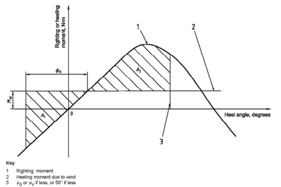
Fig 5.5 Roll resistance to waves and wind
4. Heel due to wind action (design categories C and D only)
Crafts shall be assessed in the minimum operating condition unless the ratio ŶÄǼÆĤŶÀĀÆ I ËĦËÈ, in which case the loaded displacement condition shall also be assessed.
Crafts of design categories C and D, where AÄÃ Ĥ ÄĂ AĂ, do not have to be assessed. Other crafts shall be assessed as follows.
The wind heeling moment (ÀB) shall be calculated as in 202. 3. (2), but using
ŽB = 17 m/s for design category C, and 13 m/s for design category D.
The heel angle due to the wind heeling moment, SB, shall be determined either by comparing the heeling moment with the curve of righting moments or from the formula:
SB G FÀB ĤÀÆF× SĀ
where
ÀÆ is the maximum offset-load moment, expressed in newton metres, due to the crew, see nor- mative KS V ISO 12217-1 Annex B;
SĀ is the offset-load heel angle observed due to ÀÆ . The angle SB shall be less than 0.5 SĀFĄF , derived from 2.
5. Flotation requirements
The flotation test to demonstrate adequate swamped buoyancy and stability shall be performed using the method given in normative KS V ISO 12217-1 Annex E. Where flotation materials or ele- ments are used, they shall comply with normative KS V ISO 12217-1 Annex F.
Ch 5 Stability and buoyancy Ch 5
![]()