Iranian Classification Society Rules

< Previous | Contents | Next >
Section 3 Sailing Crafts of Hull Length Greater than or Equal to 6 m
301. Requirements for monohull crafts
1. Requirements
(1) Monohull sailing crafts shall comply with all the requirements of anyone of seven options ac- cording to amount of flotation and decking, and whether the craft is fitted with suitable recesses. These options and the tests to be applied are given in Table 5.4
(2) The design category finally given is that for which the craft satisfies all the relevant require- ments of any one of these options.
(3) For crafts using option 1 or 2, the requirements shall be satisfied in the minimum operating condition unless otherwise specifically noted. If the ratio of ŶÄǼÆ /ŶÀĀÆ exceeds 1.15 then all the requirements shall be satisfied in the loaded displacement condition as well as in the mini- mum operating condition. In calculating the position of the overall centre of gravity in the load- ed displacement condition, the following shall be observed:
- fuel and water shall be located in the fixed tanks;
- provisions shall be stowed in an appropriate location;
- the mass of additional crew (crew limit less those required for ŶÀĀÆ ) shall be added at sheer-
line height at the mid-length of ÄĂ.
(4) Crafts using option 1 or 2 and fitted with provision for asymmetric ballasting whilst under way
(whether liquid or solid) shall
(A) comply with all the requirements of the selected option as indicated in Table 5.4, and
(B) comply with the requirements of 2 (3), 3 (if appropriate) and 4 for the next less demanding design category considering that the movable ballast is of whichever amount or position that
gives the most adverse result when considering each individual stability requirement.
(5) Recesses of crafts to be assigned design category A or B using option 1 of Table 5.4 shall comply with the plan-area limitations given below, unless specific account is taken of the mass
and free-surface effect of water that recesses may contain when calculating the stability characteristics.
If this special calculation option is used, righting levers shall be calculated assuming that each
recess is treated as though it had no drainage and is assumed to initially hold water to the fol- lowing percentage of its maximum (upright) capacity:
Percentage full = (60 - 240 ÁĤÄĂ)
where Á is the minimum freeboard to the coaming of the recess in question.
Such water shall be assumed to spill out as the craft heels, the righting moments being as-
sumed to be symmetrical about the
For design category A: For design category B:
upright.
plan area of all recesses (mË ) < ŊĦË ÄĂ AĂ
plan area of all recesses forward of ÄĂĤË (mË) < ŊĦË ÄĂ AĂ
plan area of all recesses (mË) < ŊĦĖ ÄĂ AĂ
plan area of all recesses forward of ÄĂĤË (mË ) < ŊĦËÈ ÄĂ AĂ
Ch 5 Stability and buoyancy Ch 5
![]()
Table 5.4 Requirements to be applied to monohull sailing crafts
Option | 1 | 2 | 3 | 4 | 5 | 6 | 7 |
Categories possible | A and B | C and D | C and D | C and D | C and D | C and D | C and D |
Decking or covering | Fully decked (1) | Any amount | Any amount | Any amount | Any amount | Any amount | Any amount |
Downflooding openings | 301. 2 (1) | 301. 2 (1) | 301. 2 (1) | 301. 2 (1) | 301. 2 (1) | 301. 2 (1) | |
Downflooding-height test | 301. 2 (2) | 301. 2 (2) | 301. 2 (2) | 301. 2 (2) | |||
Downflooding angle | 301. 2 (3) | 301. 2 (3) | |||||
Angle of vanishing stability | 301. 3 | 301. 3 | |||||
Stability index | 301. 4 | 301. 4 | |||||
Knockdown-recovery test | 301. 5 | 301. 5 | |||||
Wind stiffness test | 301. 6 | 301. 6 | |||||
Flotation requirements | 301. 7 | 301. 7 | |||||
Capsize recovery test | 301. 8 | ||||||
Note : (1) This term is defined in KS V ISO 12217-1 3.1.6. | |||||||
2. Downflooding
These requirements are to ensure that a level of watertight integrity appropriate to the design cat- egory is maintained.
(1) Downflooding openings
To be in accordance with length greater than or equal
(2) Downflooding height
(A) Test
202. 1 (1) (downflooding openings of Non-sailing crafts of hull to 6 m)
To be in accordance with hull length greater than or
(B) Requirements
202. 1 (2) (test of downflooding height of Non-sailing crafts of equal to 6 m)
(a) Determine the design category by comparing the measurements with the requirements for minimum downflooding height, as modified by (b) and (c) below, using either
(i) the method of normative KS V ISO 12217-2 Annex A, which generally gives the lowest requirement, or
(ii) Fig 5.6 which is based only on craft length.
(b) Crafts assessed using Fig 5.6 shall be permitted openings having a combined clear area, expressed in square millimetres (mmË), of not more than 50 ÄĂ Ë within the aft quarter
of ÄĂ. provided that the downflooding height to these openings is not less than 3/4 of that required by Fig 5.6
(c)
![]()
The required downflooding height for centreboard, drop keel or dagger-board casings shall be half that determined by (a) above.
Ch 5 Stability and buoyancy Ch 5
![]()
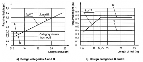
Fig 5.6 Required downflooding height
(3) Downflooding angle
This requirement is to show that there is sufficient margin of heel angle before significant quantities of water can enter the craft.
The downflooding angle to any downflooding opening (SǼA) apart from those excluded by (2) (A), which can be determined using either of the methods in normative KS V ISO 12217-2 Annex B, shall exceed the required downflooding angle (SǼFĄF ) as shown in Table 5.5.
Where a downflooding opening is protected by a higher coaming around the recess from which
it leads, the downflooding angle shall be determined to the lowest point of that coaming, see Fig B.1 in normative KS V ISO 12217-2 Annex B.
Table 5.5 Required downflooding angle
Design category | A and B | C | D |
Required downflooding angle SǼFĄF | 40 ° | 35 ° | 30 ° |
3. Angle of vanishing stability and minimum mass
These requirements are conditions. The angle of
intended to ensure an absolute minimum survival capability in severe vanishing stability for the appropriate loading conditions shall be obtained
using normative KS V ISO 12217-2 Annex C. Crafts shall normally comply with (1), but those of
design category A or B may alternatively comply with (2).
(1) Normal requirement
Crafts to be assigned to design category A or B shall comply with the requirements given in
Table 5.6.
Table 5.6 Required angle of vanishing stability
Design category | Required angle of vanishing stability (SÃFĄF ) |
A | Ŷ > 3.000 kg, SÃFĄF = (130-0.002 Ŷ). but always ≥ 100 ° |
B | Ŷ > 1.500 kg, SÃFĄF = (130-0.005 Ŷ). but always ≥ 95 ° |
C | SÃFĄF = 90 ° |
D | SÃFĄF = 75 ° |
(2) Alternative requirement for
design categories A and B
As an alternative to 301.
3 (1),
crafts may be assigned to design category A or B provided
Ch 5 Stability and buoyancy Ch 5
![]()
that
(A) SÃ ≥ 90° for design category A, or SÃ ≥ 75° for design category B;
(B) it has been shown by calculation using normative KS V ISO 12217-2 Annex D that when
the swamped or inverted craft is totally immersed. the volume of buoyancy, expressed in cubic metres (mĖ ) available from the hull structure, fittings and flotation elements is greater
than the number represented by (ŶÄǼÆĤĒÈŊ), thus ensuring that it is sufficient to support the mass of the loaded craft by a margin. Allowance for trapped air (apart from dedicated air tanks and watertight compartments) shall not be included;
(C) where compartments accessible via hatches or doors are used to demonstrate positive flotation after capsize, the compartment shall be constructed to watertightness degree 1, with hatches and doors satisfying the watertightness requirements for degree 2.
Closures to access openings into watertight compartments shall be clearly marked on both
sides:
"WATERTIGHT CLOSURE - KEEP SHUT WHEN UNDER
(D) where flotation elements are used, the requirements of KS
satisfied;
WAY"
V ISO 12217-2 Annex E are
(E) stability information similar to that required by 302. 4. is provided, except that instead of
being derived from normative KS V ISO 12217-2 Annex G, the recommended maximum wind strength for a given sail area shall be determined on the basis that the upright wind heeling moment in a gust of twice the mean wind pressure shall not be greater than the maximum righting moment at any heel angle;
(F) the warning symbols shown in Fig 5.7 are displayed at the main control position.
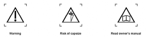
Fig 5.7 Warning symbols
4. Stability index (STIX)
The stability index is a method of obtaining an overall assessment of the stability properties of mono hull sailing crafts. Details are to be in accordance with KS V ISO 12217-2.
5. Knockdown-recovery test
This test is to demonstrate that a craft can return to the upright unaided after being knocked down. Details are to be in accordance with KS V ISO 12217-2.
6. Wind stiffness test
This test is to demonstrate that, when a sailing craft is heeled to a steady wind speed appropriate to the design category, the craft does not start flooding. Details are to be in accordance with KS V ISO 12217-2.
7. Flotation requirements
(1) Because some sailing crafts may be capsized if incorrectly handled, it shall be shown that, when the craft is inverted and/or fully flooded, either
(A) the volume of buoyancy, expressed in cubic metres, in the hull, fittings and equipment is
greater than the number represented by (ŶÄǼÆ /1,000), using the method of normative KS V ISO 12217-2 Annex D, thus ensuring that it is sufficient to support the mass of the loaded craft. Allowance for trapped bubbles of air (apart from dedicated air tanks and watertight compartments) shall not be included, alternatively;
(B) the craft when loaded to
ŶÄǼÆ
does not sink, as demonstrated by a physical test.
![]()
(2) Where compartments accessible via hatches
or doors are used to demonstrate positive flotation
Ch 5 Stability and buoyancy Ch 5
![]()
after capsize or swamping, the compartment shall be constructed to watertightness degree 1 (see KS V ISO 11812), with access closures satisfying the watertightness requirements for degree 2 of KS V ISO 12216.
Closures to access openings into watertight compartments shall be clearly marked on both sides: "WATERTIGHT CLOSURE - KEEP SHUT WHEN UNDER WAY"
Where flotation elements are used, the requirements of KS V ISO 12217-2 Annex E shall
apply.
8. Capsize-recovery test
This test is to demonstrate that a capsized craft can be returned to the upright by the actions of the crew using their body action and/or righting devices purposely designed and permanently fitted to the craft, that it will subsequently float, and to verify that the recommended minimum crew mass is sufficient for the recovery method used. Details are to be in accordance with KS V ISO 12217- 2.
302. Requirements for catamarans and trimarans
1. Requirements to be applied
Where catamarans and trimarans have ÄĂ I ÈAÆA , they shall comply with the requirements of clause
301. All other catamarans and trimarans shall comply with either
(1) 2 to 7, or
(2) capsize-recovery test as described in 301. 8, when the craft egory C or D at the discretion of the builder.
2. Downflooding openings
The requirements of 301. 2 (1) shall apply.
3. Downflooding height
The requirements of 301. 2 (2) shall apply.
4. Stability information
Since sailing multihull crafts may capsize, information on all of
shall be assigned either design cat-
the following subjects shall be pro-
vided in the owner's manual (see normative KS V ISO 12217-2 Annex F).
(1) The stability hazards to which these crafts are vulnerable, including the risk of capsize in roll and/or pitch, particularly in breaking seas.
(2) The Beaufort wind strength at which the working sail area should be reduced when sailing in
calm water in the minimum operating condition, taking account of the hazardous effects of gusts. Additional information relevant to the loaded displacement mass can also be provided if desired.
This information can be calculated using informative KS V ISO 12217-2 Annex G (which in- cludes a margin for gusts). or alternatively be derived from sailing trials. The method of deter- mination shall be stated.
If derived from sailing trials, the wind strength quoted in the owner's manual shall correspond to a wind speed of not greater than 70 % of that required to
(A) lift the windward hull of catamarans out of the water. or
(B) lift the main hull of trimarans out of the water, or submerge the leeward sidehull, which- ever occurs sooner.
(3) The choice of sails to be set with respect to the prevailing wind strength, relative wind direc- tion, and sea state.
(4) Precautions to be taken when altering course from a following to a beam wind.
5. Warning symbols
Warning symbols shall be permanently displayed at the main control position, as shown in Figs
5.8 and 5.9:
Ch 5 Stability and buoyancy Ch 5
![]()
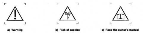
Fig 5.8 Warning symbols for catamaran
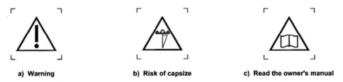
Fig 5.9 Warning symbols for trimaran
6. Buoyancy when inverted
(1) Because multihull sailing crafts may capsize, it shall be shown by calculation using normative
KS V ISO 12217-2 Annex D that, when inverted and/or fully flooded, the volume of buoy- ancy, expressed in cubic metres (mĖ), in the hull, fittings and equipment is greater than the
number represented by (ŶÄǼÆ ĤĒÈŊ), thus ensuring that it is sufficient to support the mass of the loaded craft by a margin. Allowance for trapped bubbles of air (apart from dedicated air tanks and watertight compartments) shall not be included.
(2) Where there is a means of escape provided for use in the event of inversion, it shall not com- promise the stability or buoyancy whether the craft is upright or inverted.
(3) Where compartments accessible via hatches or doors are used to demonstrate positive flotation after capsize, the compartment shall be constructed to watertightness degree 1 (see KS V ISO 11812), with hatches and doors satisfying the watertightness requirements for degree 2 of KS V ISO 12216.
(4) Closures to access openings into watertight compartments shall be clearly marked on both sides: "WATERTIGHT CLOSURE - KEEP SHUT WHEN UNDER WAY"
(5) Where flotation elements are used, the requirements of KS V ISO 12217-2 Annex E shall apply.
7. Breaking waves
To provide a degree of protection against being inverted by breaking waves, the multihull size fac- tor shall exceed the required values given in Table 5.7.
Table 5.7 Required multihull size factor
Design category | Required multihull size factor | ||
if ÄĤA < 2.2 | if 2.2 ≤ ÄĤA ≤ 3.2 | if ÄĤA ≥ 3.2 | |
A | 193,600/FÄĤA FË | 40,000 | 313,600/FÈ G ÄĤA FË |
B | 72,600/FÄĤA FË | 15,000 | 117,600/FÈ G ÄĤA FË |
C and D | not applicable | not applicable | not applicable |
NOTE For catamarans: ÄĤA = ÄĂ ĤAÆA For trimarans: ÄĤA = ËÄĂ ĤAÆA | |||
Ch 5 Stability and buoyancy Ch 5
![]()
ËĦĒÈŶÀĀÆĬJÄĂAÆA
The minimum operating mass (ŶÀĀÆ ) shall be derived from a hull mass obtained from either a weighing or calculation from an observed waterline and the lines plan.