Iranian Classification Society Rules

< Previous | Contents | Next >
Section 1 Proteciton against Falling Overboard and Reboarding
101. General
Crafts are to be designed to minimize the risk of falling overboard and to facilitate reboarding.
102. Working deck
1. Functions of the working deck
Safe access to the following areas shall be provided either via the working deck, the interior of the craft or combination thereof:
(1) craft steering including emergency steering;
(2) strong points;
(3) sail handling and trimming;
(4) interior;
(5) engine room compartment.
2. Means of protection
Protection against falling overboard from the working deck shall be achieved by applying one of the relevant options as listed in Table 6.1 or Table 6.2, taking into account the type or design of the craft and the intended use, within the limits of the design category chosen.
3. Minimum width of decks
(1) be free, continuous and not angled transversally more than 15° from the horizontal, when the craft is upright
(2) have a width of at least 100 mm for design category D, 120 mm for category C, and 150 mm for category A or B measured perpendicular
(3) to the foot stop inner limit or
(4) the lateral outer deck edge of the deck if there is no foot stop.
4. Continuity of the working deck
Working deck areas shall be connected, this may include passage through the interior. Special pro-
vision shall be made where changes in elevation or obstacles have to be surpassed. than 500 mm and obstacles higher or longer than 500 mm shall be avoided.
Steps higher
103. Tables of requirements
1. General
The requirements are presented in Tables 6.1 and 6.2. For each design category, that the corresponding safety device is required.
an “×” signifies
Ch 6 Hull Equipment Ch 6
![]()
Table 6.1 Requirements for non-sailing crafts
Safety device | Design category | |||||
A | B | B | B | C | D | |
ÄĂ > 8.5m | ÄĂ ≤ 8.5m | |||||
Slip resistant surface | × | × | × | × | × | × |
Foot-stop | × | × | × | × | ||
Handholds | × | × | × | × | × | × |
Low guard-rail or low guard-line | × | |||||
High guard-rail or high guard-line | × | × | ||||
Hooking points | × | × | ||||
Body support on high-speed craft(if relevant) | × | × | × | × | × | × |
Means of reboarding | × | × | × | × | × | × |
NOTE A handhold meeting the requirements of 111. may also be a hooking point. | ||||||
Table 6.2 Requirements for sailing crafts
Safety device | Design category | |||||
A | B and C | B and C | C | C2 | D | |
ÄĂ > 8.5m | ÄĂ ≤ 8.5m | daytime | ||||
Slip resistant surface | × | × | × | × | × | × |
Foot-stop | × | × | × | × | ||
Handholds | × | × | × | × | × | × |
Low guard-rail or low guard-line | × | |||||
High guard-rail or low guard-line | × | × | ||||
Hooking points1 | × | × | × | × | ||
Jack-line attachment points | × | × | × | |||
Means of reboarding | × | × | × | × | × | × |
NOTE 1. A handhold meeting the requirements of 111. may also be a hooking point. 2. Limited to sailing crafts, either capsize or knockdown recoverable or fitted with flotation according to Ch 5. | ||||||
104. Specific requirement for slip-resistant
1. General
areas
Working deck areas shall be slip-resistant. The spacing between slip-resistant patches shall not be greater than
(1) 75 mm for non-glazed areas
(2) 500 mm for glazed areas, unless the lateral sides of the area are fitted with foot stops
2. Requirements for trampolines and nets
Trampolines and nets which are part of the working deck shall have slip-resistant characteristics. Any opening within the working deck area having a depth greater than 1 m and not provided with
![]()
a hatch or lid shall be surrounded by guard-rails as required or fitted with trampolines or nets.
Ch 6 Hull Equipment Ch 6
![]()
105. Requirements for foot-stops
1. General
Fig 6.1 shows a few examples of foot-stops.
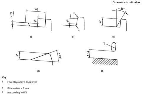
Fig 6.1 Diagram illustrating the requirements of 3, 4, 5 and 6
2. Provision of foot-stops
Foot-stops shall be provided as close as practicable to the outboard edges of the working deck. Foot-stops are not required on the following:
(1) parts of the working deck where people are not intended to walk but only sit when the craft is
underway, such as sailing craft deck edge where the crew hikes;
(2) the aft limit (perpendicular to the longitudinal axis) of monohull working deck, e.g. top of transoms;
(3) the aft limit (perpendicular to the longitudinal axis) of the rigid part of multihull working deck;
(4) front and aft beams (perpendicular to the longitudinal axis) of multihulls.
3. Minimum height and angle of foot-stop
The height of the upper edge of the foot-stop above the adjacent working deck level shall not be less than:
(1) for crafts of design category C
- 25 mm for sailing crafts,
- 20 mm for non-sailing crafts;
(2) for crafts of design category A and B
- 30 mm for sailing crafts,
- 25 mm for non-sailing crafts.
These heights are the smallest distances, measured perpendicularly to the deck, from the highest in- ner point of the foot-stop to the highest point of the deck within 100 mm of the foot-stop [see Fig 6.1 a)].
If the edges of the foot-stop have a fillet radius greater than 5 mm, the height of the foot stop shall be measured between the closest points of these fillets [see Fig 6.1 b)].
![]()
To stop the foot from slipping outboard, the angle in the internal face (or of a tangent to it) shall
Ch 6 Hull Equipment Ch 6
![]()
not be more than 30° from the vertical [see Fig 6.1 c)], except on non-sailing crafts using the de- vice described in 4 (for non-sailing crafts only).
4. Foot-stops made of angled surfaces
Angled surfaces foot-stops are allowed on non-sailing crafts of design categories C and D. These surfaces shall have an inclination of not less than 20° from the horizontal and a height according to 3 [see Fig 6.1 d)].
These angled surfaces shall be slip-resistant.
5. Maximum foot-stop clearance between deck and foot stop
If there is a vertical clearance between deck and foot-stop level the open spaces between the deck level and the bottom of the lowest foot-stopping point shall not be greater than 40 mm [see Fig 6.1 e)].
Ex) Soft or rigid line parallel to the working deck.
6. Continuity on the working deck level in way of the foot-stop
In order to guarantee foot-stopping action there shall be no step in the working deck level greater than 15 mm within 100 mm from the foot-stop [see Fig 6.1 a)].
7. Gaps in the foot-stop rail
Gaps in the foot-stop rail are allowed for stanchions, pulpit feet, cleats, etc. or for water drainage, but each gap shall not be greater than 100 mm to the edge of the adjacent fitting or foot stop rail. This distance shall be measured parallel to the foot stop general line.
Fittings providing foot-stopping action are considered to be local foot-stops.
106. Requirements for handholds
1. Location in way of side decks
(1) Handholds fitted less than 300 mm inboard from the outer working deck edge shall be placed at least 350 mm above deck level, but not higher than the adjacent superstructure.
(2) On the route along the outer edges of the working deck, the maximum distance between two adjacent handholds shall not exceed 1.5 m.
107. Common requirements for low and high guard-rails and guard-lines
1. General
Guard-rails may be required, either low guard-rail/low guard-line (Y ≥ 450 mm) or high guard-rail/ high guard-line (Y ≥ 600 mm) as specified in 2.
Guard-rails shall completely surround the outer edges of the working deck except in the transversal direction as permitted by 3, 6 and 8.
2. Height of guard-rails or guard-lines
Low guard-rails/ low guard-lines shall have a height of at least 450 mm. High guard-rails/ high guard-lines shall have a height of at least 600 mm.
If there are discontinuities in the working deck level, the vertical gap between the lowest guard-rail/guard- line and the deck or foot-stop, coaming, bulwark, etc., whichever is higher, shall not be greater than
- 560 mm for low guard-rail or low guard-line [see Fig 6.2 a)];
- 380 mm for the intermediate line of a high guard-rail or guard-line [see Fig 6.2 b)].
The length of these discontinuities in the main deck area shall not be greater than 600 mm, when measured parallel to the guard-rail/guard-line mean direction [see Figs 6.2 a) and b)].
Ch 6 Hull Equipment Ch 6
![]()
3. Intermediate lines, vertical spacing and maximum gap
On non-sailing crafts, rigid high guard-rails and pulpits need not be fitted with intermediate lines.
If high guard-rail/guard-lines are installed, an intermediate guard-rail shall be fitted, the gap between this intermediate line and the deck, foot, stop, bulwark, etc, whichever is higher, shall not be great- er than 300 mm.
As an alternative, the intermediate line may be replaced by any device limiting the gap between two adjacent protections below 380 mm, in any direction [see Fig 6.2 c)].
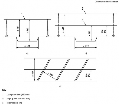
Fig 6.2 Diagram illustrating the requirements of 2 and 3
4. Risk of falling overboard from elevated parts
Even when protected from falling overboard by guard-rail/guard-line there board from higher parts of the working deck (See Fig 6.3.).
Therefore
- any part of the working deck located higher than ĂË from the adjacent shall at least be equipped with foot-stop according to 107.;
is a risk of falling over-
part of the working deck
- any part of the working deck located higher than ĂË from the adjacent part of the working deck shall at least be equipped with foot-stop according to 107. and guard-rails/guard-lines having the same height as at the outer periphery of the deck.
Ch 6 Hull Equipment Ch 6
![]()
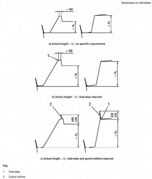
Fig 6.3 Diagram illustrating the requirements of 4
ĂË and ĂË are function of the height of the guard-rail/guard-line and defined in Table 6.3.
Table 6.3 Values of ĂË and
ĂË according to guard-rail/guard-line height
Dimensions in millimetres
Guard-rail/line height | ĂË | ĂË |
450 | 700 | 1200 |
600 | 900 | 1500 |
5. Openings in guard-rails/guard-lines
To facilitate boarding or reboarding of people or equipment, openings in the guard-rail/guard-lines are allowed, provided that permanently fixed and quickly operable mobile sections are fitted in way
Ch 6 Hull Equipment Ch 6
![]()
of these openings. These sections shall be designed not to open inadvertently.
Openings in guard-rails/guard-lines are also allowed for the passage of sails, provided that there is no gap transversally and that the space between the rails does not exceed 150 mm.
6. Bow pulpits for sailing crafts
Bow pulpits may be open but the opening between the pulpit and any part of the craft shall never be greater than 360 mm.
7. Transom guard-rails/guard-lines for sailing crafts
(1) On crafts where a high guard-rail/guard-line is required:
- the aft pulpits in way of the transom or guard-line support shall have at least the required 600 mm height;
- the transversal line need not meet the requirements of 1, 2 and 3 provided that
- the height of the line is at least 450 mm above any part of the seat;
- the height of the line is at least 800 mm above any part of the cockpit bottom local lev- el;
- there is a handhold according to 106. allowing an athwartship grip line higher than 600 mm not farther than 1,250 mm from the line end;
- the horizontal distance between two adjacent supports is not greater than 2,500 mm. See Fig 6.4.
(2) On crafts where a low guard-rail/guard-line is required:
- the aft pulpits in way of the transom or guard-line support shall have at least the required 450 mm height;
- the transversal line need not meet the requirements of 1, 2, 3 provided that
- the height of the line is at least 300 mm above any part of the seat level;
- the height of the line is at least 650 mm above any part of the cockpit bottom local lev- el;
- there is a handhold according to 106. allowing an athwartship grip line higher than 600 mm not farther than 1,000 mm from the line end;
- the horizontal distance between two adjacent supports is not greater than 2,000 mm.
See Fig 6.4.
8. Forward cross beams of sailing catamarans
On sailing catamarans, the wire/rod and stanchion bracing on forward cross beam may be regarded as a guardrail/guard-line, even if its height varies from the minimum required height to zero at the beam end. The minimum height of this wire/rod at centreline shall be according to the option of Table 6.2 for guard-rail/guard-line height.
Similarly, the height of the longitudinal guard-rail/guard-line system on the outer edges of the hulls may diminish to zero in way of the forward beam. As long as the greatest distance between possi- ble handhold points on the transverse and longitudinal guard-rails shall not be greater than 0,75 m.
9. Central hull of sailing trimarans
On sailing trimarans, guard-rails/guard-lines may be omitted on the central hull in the areas where a person falling from the working deck would land on a trampoline, which shall have a width of at least 700 mm in these areas.
Ch 6 Hull Equipment Ch 6
![]()
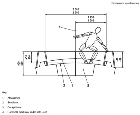
Fig 6.4 Transom diagram facing aft, illustrating the requirement of 7
108. Requirements for stanchions or guard-line supports
1. Spacing
The spacing between stanchions or guard-line supports shall not be greater than 2,2 m.
2. Fixture and disposition of stanchion and line supports
Stanchions/line supports shall not be angled outboard more than 10° from the vertical, at any point above 50 mm from the deck.
109. Requirements for hooking points
1. General
Hooking points are eye, fitting, or any device to which people can clip directly a safety harness and be able to move around an area of the working deck.
2. Location
Hooking points shall be located as follows :
(1) within 1 m of the edge of the main access hatch/door;
(2) within 2 m of all outside steering positions;
(3) within 2 m of the mast of sailing crafts;
(4) within 2 m of the winch positions of sailing crafts;
(5) within 2 m of the windlass or towing strong point(s). Hooking points shall be located no more than 3 m apart.
Habitable sailing multihulls of design category A and B shall be fitted with at least one hooking point in the vicinity of each escape hatch, to be used if the craft is in the inverted position.
Ch 6 Hull Equipment Ch 6
![]()
3. Size
In order to allow a correct closing of the harness hook, any hooking point shall be inscribed with- in a circle of 15 mm diameter.
110. Attachment points for jack-lines
1. General
Jack-line means flexible line or rigid bar intended for attachment of the safety harness allowing safe movement of the crew along its length when attached.
2. Fitting
Attachment points for jack-lines shall be fitted on deck, port and starboard to provide secure fixing for jack-lines. These lines shall be long enough to allow the movements on the working deck needed for craft operation.
Jack-lines may be fitted in sections, but each section of jack-line shall be as long as practicable. Attachment points shall be fitted at the ends of each section.
111. Body support on high-speed crafts
1. General
High-speed crafts shall be fitted with means of support for each of its occupants, when the craft is underway, limiting the risk of being thrown overboard in case of sharp turns, strong acceleration, or movements in the sea.
To provide support, one of the following option shall be chosen, for each person:
- one handhold plus body support as required in 2;
- two handholds allowing simultaneous gripping of both hands.
2. Body support
If the occupants are seated, the body support shall have a height of no less than 120 mm above the rigid bottom of the seat or where a cushion is if fitted, with the cushion fully compressed.
If the occupants are standing or leaning, the body support may only provide support for the back or the torso.
If the occupants are sitting riding astride a seat, i.e. riding, the body support may be provided by the action of the knees.
112. Means of reboarding
It shall be equipped with a specific means of reboarding from the water, e.g. ladders, steps, hand- holds, brackets.
The ladders have the lowest point serving as foot step located at least 300 mm below the waterline.
Reboarding means is rigid or flexible fitting or part of the hull which allows a person to reboard without assistance
113. Requirements for strength
Requirements for strength of each safety device shall comply with KS V ISO 15085.
114. Owner’s manual
The owner’s manual provided with the craft shall indicate the items specified in Table 6.4.
Ch 6 Hull Equipment Ch 6
![]()
Table 6.4 Requirements for owner’s manual
Subclause in ISO 15085 | Required indication in owner’s manual |
102. 1 | If appropriate, a text or a sketch in the owner’s manual shall indicate the working deck area(s) defined by the craft builder. |
Table 6.2, Design Category C(Daytime) | A sentence in the owner’s manual shall indicate that the craft is only intended for daytime sailing and not for use at night. |
107 | If relevant, information on maintenance requirements for guard-lines pointing out the need for periodic inspection of synthetic wires for UV degradation and chafe that might necessitate replacement. |
112 | Description of the means of reboarding. |