Iranian Classification Society Rules

< Previous | Contents | Next >
Section 2 Windows, Portlights, Hatches, Deadlights and Doors
201. Terms
For the purposes of this Section, the following terms and definitions apply.
1. Appliance location area
Area of the craft where the appliance is fitted
See KS V ISO 12216 Annex A for sketches showing examples of appliance location areas.
(1) Area I
Part of the hull sides situated above waterline, i.e. up to its intersection with the weather deck (for decked craft), or the upper edge of the hull (for open craft or partially decked craft), but only to the following upper boundary:
- a horizontal line located at the height YÅ above waterline in the rear half of the waterline (see Fig 6.5);
- a sloped line having a height YÅ at mid waterline, and a height 1.2 YÅ at the waterline, with
the front end of
- YÅ G ÄĂ ĤËË for sailing monohulls.
- YÅ G ÄĂ ĤËĒ for non-sailing crafts, sailing catamarans and central trimarans.
hull of sailing
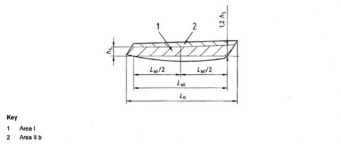
Fig 6.5 Limits of Areas I and II b
(2) Area II a
![]()
Area, other than Area I, where persons are liable to walk or step, such as decks, super- structures, cockpit soles, at an inclination of less than 25° to the horizontal in a longitudinal di- rection, and at an inclination of less than 50° to the horizontal in the transversal direction re- spectively for sailing monohulls, or 25° for multihulls
Ch 6 Hull Equipment Ch 6
![]()
(3) Area II b
Areas from the hull sides not belonging to Area I
(4) Area III
Area, other than Area I or II
(5) Area IV
Parts of Area III protected from the direct impact of sea or slamming waves
2. Type of plate end connection
See KS V ISO 12216 Annex B for sketches showing examples of types of plate end-connection.
(1) Semi-fixed (SF plate)
Plate fixed in a way to restrict deflection and prevent lateral movement at its boundaries
(2) Simply supported (SS plate)
Plate that can deflect at its boundaries and/or perform lateral movement
(3) Flexibly connected plate
Simply supported plate where the connection is achieved by an elastic support around the pe- rimeter of the plate
202. General requirements
To avoid flooding, all appliances shall be designed and fixed to prevent substantial ingress of water when closed.
1. Minimum degree of watertightness
The required minimum degree of watertightness of an appliance is category. These requirements are given in Table 6.5.
a function of the craft's design
Table 6.5 Minimum degree of watertightness
Type of craft | Appliance location area | Type of appliance | Design category | |||
A | B | C | D | |||
Any | Area I | Any | 2 | 2 | 2 | 2 |
Any | Area II | Any | 2 | 2 | 3 | 4 |
Any | Area II | Sliding companionway hatch | 3 | 3 | 3 | 4 |
Any | Area III | Any | 3 | 3 | 3 | 4 |
Sailing monohull | Area IV | Any | 3 | 3 | 3 | 4 |
Non-sailing + Multihull | Area IV | Any | 3 | 3 | 4 | 4 |
2. Additional requirements related to watertightness
(1) Sliding appliances
Sliding appliances shall not be used in Area I.
(2) Deck hatches of trimaran outrigger hulls
Hatches fitted on the decks of trimaran outrigger hulls shall not be sliding appliances.
203. Plate materials
1. General
Appliance plates shall be made of
(1) A transparent glazing material, such as poly(methyl)methacrylate (PMMA), polycarbonate (PC), tempered glass, chemically reinforced glass or laminated glass, or
(2) A non-transparent plate material, such as plywood (PW), glass-fibre reinforced thermosetting plastic (GRP), aluminium alloy, steel, etc.; or
![]()
(3) Any other material of strength and stiffness equivalent to those cited above.
Ch 6 Hull Equipment Ch 6
![]()
2. Acrylic sheet materials
Poly(methyl)methacrylate (PMMA) made with a technique have mechanical properties and resistance to ageing at least
3. Glass
other than the casting procedure shall equal to those of cast PMMA
The use of glass is restricted to (1) and (2) plus 204. 1 (1) (A) for use of simply supported plates, 204. 3 (1) (D) for use in Area I and 204. 3 (2) for use in Area II.
(1) Monolithic glass
Monolithic glass shall only be made of tempered glass, or chemically reinforced glass.
(2) Laminated glass
The glass plies used in laminated glass can be made of any type of glass.
204. Specific requirements
1. End connection and location of plate
(1) Simply supported plates
(A) Plates in Area I
Simply supported plates shall not be used in Area I:
- on sailing monohulls in design categories A and B and sailing multihulls in design cat- egory A;
- on non-sailing crafts in design category A.
On other types of craft and design categories, simply supported plates may be used provided that all the following conditions are met:
- the glazing material is PMMA or PC (see clause 203.) ;
- the plate thickness is equal to 1.3 times the one required by clause 205. ;
- the fixing devices of the plate (hinge bolts, fixing knob, etc.) are not spaced more than 250 mm.
The above restrictions of use need not be considered if the appliance is equipped with a
deadlight meeting the requirements of 3 (6).
(B) Flexibly connected plates
Flexibly connected plates may only be used on non-sailing crafts of design categories C and
D in Areas III and IV.
(2) Semi-fixed plates
(A) Plates made of material other than glass
Semi-fixed plates may be used in crafts of all design categories and in all location areas with the restrictions of the special requirements given in 3.
This type of end connection can be achieved by one of the following means.
(a) Connected with a counter frame: The edge fixity is achieved by pinching the plate at its periphery between the craft shell or a frame and a counter frame. The counter frame shall be mechanically fastened and/or glued to the structure of the craft.
(b) Connected by gluing: The edge fixity is achieved by gluing the plate at its periphery to the craft shell, to the structure of the craft or to a frame. This gluing can either be in a rabbet or a face, edge gluing or any combination of these gluing methods.
(c)
Connected by direct fastening: The edge fixity is achieved by fastening the plate inside its periphery to the shell, the structure of the craft or to a frame by correctly spaced and sized mechanical fasteners. These fasteners may be bolts, rivets, self-tapping screws
or any adequate mechanical fasteners.
(B) Plates made of glass
Metal to glass contact shall be avoided.
2. Fastening requirements
(1) Fastening of plates and frames
Plates and frames can be fastened by mechanical means, glue or elastomer joints. All types of fastening shall ensure watertightness of the plate or frame, and resistance to loads due to nor- mal operating pressure.
Every part of the mechanical elements connecting appliances to the rest of the craft shall be ca- pable of withstanding, without breaking, twice the force induced by the pressure loads defined
in 205. This requirement shall be verified for inwards opening appliances, where hinges, locks or any other part of the link chain between the plate and the support shall be checked by cal-
Ch 6 Hull Equipment Ch 6
![]()
culation or testing in accordance with KS V ISO 12216 Annex D D.2.
(2) Fastening of semi-fixed plates
Mechanical fasteners shall not induce parasitic stresses due to deflection or temperature changes, nor stress concentration or stress raising.
Additional stresses brought by cold forming shall be considered when determining the plate scantlings in 205.
(3) Fastening of glued plates
Glued joints shall be resistant to (or protected against) sunlight (UV, heat, etc.) and all environ- mental effects or cleaning chemicals normally encountered in the manufacture and use of the craft.
Glued joints shall fulfil the requirements of one of the following items:
(A) the inside pressure test (KS V ISO 12216 Annex D D.3.2);
(B) the separation test (KS V ISO 12216 Annex D D.3.3);
(C) the manufacturer's gluing procedure and conditions are followed and the bond strength checked by calculation to meet test pressure in KS V ISO 12216 Annex D D.3.2.2.
The above requirements shall be verified after any change in material or gluing procedure. Plates, with or without framing, are considered glued if they are fastened with mechanical de-
vices, such as bolts, rivets or screws, spaced more than 20 times Ź, where Ź is the nominal plate thickness defined in 205.
3. Special requirements
(1) Appliances fitted in Area I
(A) Height above waterline and maximum short side dimension
The lower edge of any opening appliance shall be placed at least 200 mm above the water- line, the craft being in the fully loaded ready-far-use condition and upright. These opening appliances shall in any case be located according to the relevant requirements of Ch 5.
The small unsupported dimension Ẅ (or the equivalent of Ẅ) of any appliance (see KS V ISO 12216 Annex C) placed in Area I shall not exceed 300 mm.
The above requirements do not apply to escape hatches of sailing multihulls, or designated
escape hatches, when required by KS V ISO 9094.
(B) Opening side
All opening appliances shall open inwards, with the exception of multihull escape hatches or designated escape hatches, when required by KS V ISO 9094.
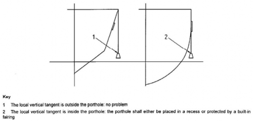
(C) Protection
On crafts of design categories A and B, no part of the plate or its framing shall extend
outside the local vertical tangent to the hull, deck, rubbing strake, fixed fender, or of a built-in fairing which is an integral part of the hull. Fig 6.6 explains this requirement.
(D) Use of glass
Fig 6.6 Sketch explaining the requirement of (C)
Glass shall not be used on sailing crafts of all design categories and on non-sailing crafts of design categories A and B, unless the plate is made of high-impact-resistance glass, or if
Ch 6 Hull Equipment Ch 6
![]()
the appliance is equipped with a deadlight meeting the requirements of (6). High-impact-re- sistant glass types are listed in normative KS V ISO 12216 Annex E.
(2) Appliances fitted in Area II a
(A) Use of glass
On non-sailing crafts, the usage of monolithic and laminated glass is accepted without restriction.
On sailing crafts, neither monolithic nor laminated glass shall be used forward of the mast or foremast, unless the plate is made of high-impact-resistance glass, or if the appliance is
equipped with a deadlight meeting the requirements of (6). High-impact-resistance glass types
are listed in KS V ISO 12216 Annex E.
This restriction need not be considered if the plate is protected against shocks by an ad- equate device.
(B) Tests on hinged deck hatches
(a) Unintentional stepping test
The test is performed on a hinged deck hatch fixed to a rigid flat support of di- mensions twice those of the hatch, as shown in Fig 6.7.
The hatch is open in any position, up to its maximum operating position, and shall be able to withstand a concentrated force of 750 N applied anywhere on the outside edge
of the hatch, without permanent deformation or damage to the hatch, its framing or hinge. The hatch will normally close under the applied force, and the system that is
used to maintain the hatch open may be damaged. The hatch is considered to fulfil the
requirements of this test if the integrity of the hatch, and its closing and watertightness capabilities, are maintained.
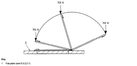
Fig 6.7 Unintentional stepping test
(b) Rope jamming test
The test is performed on the same test device and loading as in (a), but with a 14 mm,
three-strand polypropylene rope simultaneously
6.8.
The test is considered as passed if there is no plate, its framing or hinges.
jamming both sides, as shown in Fig
permanent deformation or damage to the
Ch 6 Hull Equipment Ch 6
![]()
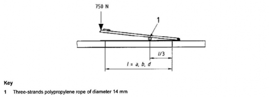
Fig 6.8 Rope jamming test
(c) Hatch and hinge strength test
The test is performed on the same test device as in (a), with the hatch open at 90°, as shown in Fig 6.9.
Apply a twisting torque made by two parallel and opposite forces of 200 N, acting on
the two outside corners (or horizontal diameter) of the opening part of the hatch.
The test is considered as passed if there is no permanent plate, its framing or hinges.
deformation or damage to the
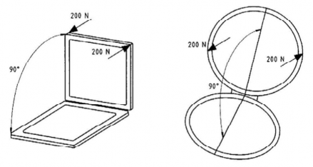
Fig 6.9 Hatch and hinge strength test
(3) Sliding appliances
(A) Rabbet depth
The depth of the rabbet shall be sufficient to prevent any disengagement of the plate under the pressure loads defined in 205., taking into account the size of the appliance, the materi-
al of which it is made, and the rigidity of the structure it is fixed on. For unframed plates made of PMMA, PC, or materials with similar modulus of elasticity, this depth shall be at
least 12 mm.
(B) Stops
The appliance shall be fitted with stops at each end of its stroke to prevent any disengage-
ment of the sliding part of the frame.
(4) Doors made with removable sections: washboards
Doors made with removable sections, usually called "washboards", shall be
(A) fitted with a device to keep them in position, when in use, and to be at least operable from inside, and
(B) stored inside the craft in the vicinity of the door opening, and easily reached without the
Ch 6 Hull Equipment Ch 6
![]()
use of tools.
Craft of design category A shall be equipped with a device connecting the boards together when not in use.
(5) Locking system
Any appliance shall have a locking device which maintains it in a closed position, operable at least from inside.
On doors, this system shall be operable from both sides.
In crafts of design categories A and B, if the companionway door is used together with a com- panionway hatch, the locking device need only be efficient when both the door and the hatch are closed together. In this case, if the companionway door is made with washboards, the lock-
ing device may only act between the upper panel of the washboard
(6) Deadlights
and the hatch.
Any part of a deadlight shall meet the requirements of 405. and 407. 2. Deadlights of win- dows fitted in Area I. if required, shall be permanently attached to the appliance, its framing,
or the craft structure, and be operative even in the case
window.
(7) Multihull escape hatches
(A) Minimum dimensions
of rupture of the opening part of the
On crafts with ÄĂ > 12 m, the multihull escape hatches shall have the following minimum clearing characteristics:
- circular shape: diameter of at least 450 mm;
- any other shape: a minimum dimension of 380 mm and 0,18 mË minimum area. The hatch shall be big enough for a 380 mm diameter circle to be inscribed.
(B) Material
Glass shall not be used, unless it is high-impact-resistance glass. High-impact-resistance glass types are listed in KS V ISO 12216 Annex E.
(C) Opening and hinge disposition
Multihull escape hatches shall be free to open from the inside and the outside when secured but unlocked.
The hinge or hinges of an escape hatch that opens outwards shall be such that the hatch
cannot be torn out by the action of the sea if it is partially, or totally, opened.
(8) Commercially available appliances
Commercially available appliances shall, at the time of purchase, have an information notice which indicates, for the benefit of the fitter and consumer, the upper design category, craft type
and location area allowed. This notice may be a sticker glued on the appliance, a label on the
appliance box, a leaflet or any other type of information device.
205. Scantling determination of non-stiffened plates See clause 7. of KS V ISO 12216.