Iranian Classification Society Rules

< Previous | Contents | Next >
Section 3 Watertight Cockpits and Quick-draining Cockpits
301. Scope
This section specifies requirements for cockpits and recesses to be designated either as "watertight" or as "quick-draining".
302. Definitions
For the purposes of this section, the following terms and definitions apply.
1. Cockpit and recess
Any area that may retain water, however briefly, due to rain, waves, craft heeling, etc.
2. Cockpit sole
Essentially horizontal surface(s) of the cockpit on which people normally stand
Ch 6 Hull Equipment Ch 6
![]()
3. Cockpit bottom
Lowest surface of the cockpit sole where water collects before being drained
4. Bridge deck
Area just outside the companionway opening and above the cockpit bottom, onto which people nor- mally step before entering the accommodation
5. Closing appliance
Device used to cover an opening in the cockpit, hull or superstructures
6. Cockpit water-retention height(YÆ )
Height of the water contained in the cockpit measured between the cockpit bottom and the point of overflow outboard, the craft being upright, at rest and fully loaded
7. Cockpit bottom height(ĂA )
Height of the cockpit bottom above the waterline. the craft being upright, at rest and fully loaded
8. Cockpit volume(ÃÆ)
Volume, in cubic metres, of water that can be instantaneously contained in the cockpit before dis- charge, which is the volume below YÆ
9. Cockpit volume coefficient(ÝÆ )
Ratio between the cockpit volume and the reserved buoyancy
ÃÆ
ÝÆ G JÄ ĂA maxÁÀ
303. General requirements
1. Loading and measurement conditions
The loading conditions for the subclauses 2 to 4 are "fully loaded ready-for-use" as defined in KS V ISO 8666. In some cases, the mass of water contained in specific volumes shall be added to this loading (see 304. 2 (1) and (2)).
The measurement or calculations shall be made with the craft upright and at rest in smooth water.
2. Requirements for "watertight" cockpits and recesses
A "watertight" cockpit or recess shall
- have its sills in accordance with 306.
- show a degree of watertightness in accordance with 307.
3. Requirements for "quick draining" cockpits and recesses
A "quick-draining" cockpit or recess shall
- have its bottom height ĂA above the waterline in accordance with 304.
- have its draining devices in accordance with 305.
- have its sills in accordance with 306.
- show a degree of watertightness in accordance with 307.
4. Closing appliances
Closing appliances fitted in watertight cockpits and quick-draining cockpits, and giving access to the interior of the craft, shall fulfil the requirements of Ch 2 and of 307.
Ch 6 Hull Equipment Ch 6
![]()
304.
Requirements for quick-draining cockpit bottom
1. Minimum cockpit bottom height,
The minimum cockpit bottom height,
ĂAĦmin
ĂAĦ min , above the waterline shall be according to Table 6.6.
Table 6.6. Minimum height, ĂAĦmin, of the cockpit bottom
Dimensions in metres
Design category | Height, ĂAĦ min |
A | 0.15 |
B | 0.1 |
C | 0.075 |
D | 0.05 |
NOTE Greater heights than these minimum values may be required to fulfil the maximum acceptable draining time according to 305. 2 | |
2. Exception to 6.1 for recesses or lockers
(1) Exception up to 10 % of cockpit bottom area
Surfaces up to a total 10 % of the horizontal projection of the cockpit bottom are not required to comply with 1. Among these surfaces, those containing water after the cockpit has drained will be considered full of water when assessing the fully loaded condition.
(2) Lockers in the cockpit bottom Lockers placed in the cockpit bottom
- which are intended for the storage of liferafts, ice, fish, baits, etc., and
- which are watertight towards the interior of the craft, and
- whose closing appliances do not fulfil all the requirements of 303. 3,
305. Requirements for drainage of quick-draining cockpits
1. Cockpit drainage
(1) General
Draining shall only be by gravity.
(2) When the craft is upright
When the craft is upright, at least 98 % of the cockpit volume shall drain, excluding any recess in accordance with the exceptions of 304. 2.
(3) When the craft is heeled
The requirements in (A) and (B) shall be fulfilled when the craft is heeled to both port and starboard.
(A) Sailing monohulls
On sailing monohulls, drainage shall be provided for at least 90 % of ÃÆ at the lesser heel angle of
- 30° heel, or
- when the deck at side begins to touch the water.
(B) Non-sailing crafts and multihulls
On non-sailing crafts and multihulls, drainage shall be provided for at least 90 % of ÃÆ at 10° heel.
2. Draining time
The draining time is the time needed to drain the cockpit from the full height of water, YÆ , down to a remainder of 0,1 m above cockpit bottom.
The draining time shall be measured or calculated with every appliance closed.
If the draining section. expressed in square metres, is greater than or equal to 0,05 ÃÆ , it is consid- ered large enough to fulfil the requirements and does not require a draining time assessment.
Ch 6 Hull Equipment Ch 6
![]()
For other drain configurations, the draining time shall be assessed, and shall not be greater than
Źmax
given by the formulae in Table 6.7 or by the curves in Fig 6.10.
Table 6.7 Maximum acceptable draining time, Źmax
Time in minutes
Design category | Źmax |
A | 0.3/ÝÆ but not greater than 5 |
B | 0.45/ÝÆ but not greater than 5 |
C | 0.6/ÝÆ but not greater than 5 |
D | 0.9/ÝÆ but not greater than 5 |
The cockpit volume, ÃÆ , shall be measured from the cockpit bottom up to the top of YÆ , eventual exception of 304. 2, assuming that all closing appliances and drains are closed.
with the
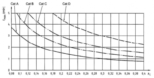
Fig 6.10 Maximum acceptable draining time
Źmax
according to ÝÆ
and design category
3. Number of drains
A quick-draining cockpit shall have at least two drains, one port and one starboard, unless opening enables drainage when the craft is heeled to both port and starboard, as required in 1.
4. Minimum drain dimensions
(1) Internal dimensions of the drain
one
Drains with a circular cross section shall have a diameter of at least 25 mm. Drains with other cross-sectional shapes shall have a cross-sectional area of at least 500 mmË and a minimum di-
mension of 20 mm.
(2) Eventual protective grids
If the drains are equipped with systems preventing loose objects from falling into the draining system, one shall be aware that a grid of small holes is more prone to be clogged than the drain itself.
If the minimum passage dimension inside any part of these devices has at least a section of 125 mmË (or a diameter of 12 mm), and the total entry cross-section is at least 1.5 times the
cross-section of the drain, Table 6.8 may be used for calculation of the draining time.
Ch 6 Hull Equipment Ch 6
![]()
If the above conditions are not met, the head losses from the protection grid shall be considered. See KS V ISO 11812 Annex D.
5. Centreboard housings and other types of drain
Centreboard housings and other types of aperture may be used as drains if they are designed for this purpose.
6. Drain fitting
The drain outlet running through the hull shall either be located above the waterline or, if below the waterline, be fitted with seacocks (see 7), unless the drain outlet is an integral part of the hull extending from the outlet up to at least 0.75 ĂAĦ min above the waterline.
Fig 6.11 shows a drain outlet integral with the hull.
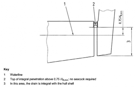
Fig 6.11 Drain outlet as an integral part of the hull
7. Drain piping design and construction
The scantling and design of drains shall take into account all the loads subjected.
Drain piping shall be protected against damage from loose objects stowed being kicked or stepped on.
to which they may be in the craft and against
Drain piping shall not trap water and shall only be used for cockpit drainage. This requirement does not apply to drains fitted in centreboard housing or outboard wells and trunks.
Seacocks, through-hull fittings, and associated components shall comply with the requirements of
Ch 2 or Ch 3.
8. Draining time assessment
(1) General
The draining time shall be determined either by measurement of the actual draining time, or by calculation.
(2) Measurement of the draining time
The craft shall be placed near the fully loaded displacement and corresponding design trim.
The cockpit is filled with water up to YÆ . and the draining time to empty the cockpit between YÆ and 0.1 m of water remaining in the cockpit is measured. This latter height shall be meas- ured above the centre of the bottom surface of the cokpit.
(3) Calculation of the draining time
Ch 6 Hull Equipment Ch 6
![]()
A quick and approximate method of calculating the draining time calculation is given in (4). Simplifications in this method may lead to small differences between measured and calculated draining time, but both methods are considered valid.
More thorough methods of calculation are specified in KS V ISO 11812 Annex C.
If the arrangement of cockpit and drains does not correspond to the cases of (4) or the methods of KS V ISO 11812 Annex C. the calculation method used shall be based on a practical test on a similar arrangement.
(4) Quick method of calculation for cockpit fitted with two drains
(A) Step 1: Determination of the required maximum draining time Źmax
Determine
Źmax
using ÝÆ G ÃÆ Ĥ FÄĂ Amax ÁŶẀŴŸF , i.e. the cockpit volume coefficient in accord-
ance with 2.
(B) Step 2: Determination of the reference draining time, ŹZẀX
Calculate
ŹZẀX G Źmax ĤÃÆ
which is the reference draining time (without head loss) for a set of
two drains.
(C) Step 3: Determine whether the drain outlet is above or below the waterline
Determine whether the drain outlet is above or below the waterline when the cockpit is full. If the drain outlet is above the waterline when the cockpit is empty and below it when the cockpit is full, one shall either conservatively consider that the drain is always below the waterline, or make the calculation in both cases and calculate the final time by interpolation. Fig 6.12 shows some drain arrangements, but other arrangements may be used.
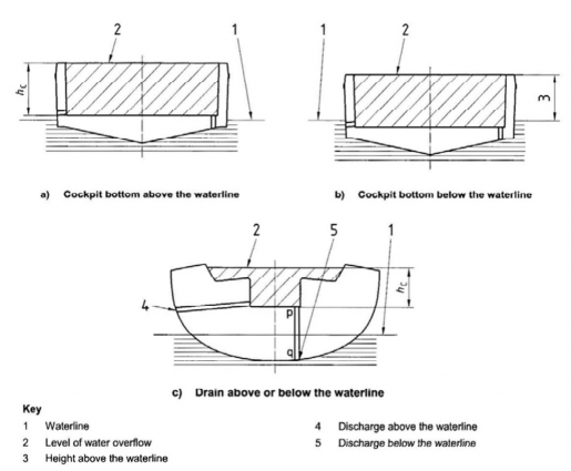
Fig 6.12 Examples of some drain arrangements
(D) Step 4: Determination of the required drain diameter
Table 6.8 gives the approximate draining time for six cases: drain above or below terline, no elbow or two elbows, and freeing port with and without a flap.
the wa-
Enter the line corresponding approximately to the cockpit configuration and choose the drain
diameter giving a draining time used.
ŹZẀX
corresponding to the requirements. Interpolations may be
Ch 6 Hull Equipment Ch 6
![]()
Table 6.8 Drain diameter as a function of ŹZẀX and typical drain arrangement
Typical drain arrangement | Values of ŹZẀX (min) | ||||||||||||||||||
Drain outlet above BÄ , no elbow | 8.8 | 5.8 | 4.1 | 3.0 | 2.3 | 1.8 | 1.5 | 1.2 | 1.0 | 0.9 | 0.8 | 0.7 | 0.5 | 0.4 | 0.3 | 0.3 | 0.2 | 0.2 | 0.2 |
Drain outlet above BÄ , two elbows | 10.0 | 6.7 | 4.7 | 3.5 | 2.7 | 2.2 | 1.8 | 1.5 | 1.3 | 1.1 | 0.9 | 0.8 | 0.6 | 0.5 | 0.4 | 0.4 | 0.3 | 0.3 | 0.2 |
Drain outlet above BÄ , no elbow | 10.8 | 7.2 | 5.1 | 3.9 | 3.0 | 2.4 | 2.0 | 1.6 | 1.4 | 1.2 | 1.0 | 0.9 | 0.7 | 0.6 | 0.5 | 0.4 | 0.3 | 0.3 | 0.2 |
Drain outlet above BÄ , two elbows | 11.8 | 7.9 | 5.7 | 4.3 | 3.3 | 2.7 | 2.2 | 1.8 | 1.5 | 1.3 | 1.2 | 1.0 | 0.8 | 0.6 | 0.5 | 0.4 | 0.4 | 0.3 | 0.3 |
Freeing port above BÄ , no flap | 10.1 | 7.0 | 5.2 | 3.9 | 3.1 | 2.5 | 2.1 | 1.8 | 1.5 | 1.3 | 1.1 | 1.0 | 0.8 | 0.6 | 0.5 | 0.4 | 0.4 | 0.3 | 0.3 |
Freeing port above BÄ , withflap | 15.2 | 10.5 | 7.7 | 5.9 | 4.7 | 3.8 | 3.1 | 2.6 | 2.2 | 1.9 | 1.7 | 1.5 | 1.2 | 0.9 | 0.8 | 0.7 | 0.6 | 0.5 | 0.4 |
Drain diameter Ẁ(mm) two drains | 25 | 30 | 35 | 40 | 45 | 50 | 55 | 60 | 65 | 70 | 75 | 80 | 90 | 100 | 110 | 120 | 130 | 140 | 150 |
However, for a non-circular drain section, the section area shall be the same drain.
as that of a circular
306. Requirements for sills
1. Sill height for watertight cockpits
Watertight cockpits shall have no opening below the height YÆ .
2. Sill height and other requirements for quick-draining cockpits
(1) Sill-height measurement
When measuring the sill height, all closing appliances shall be considered to be closed, with the exception of companionway door(s). The sill height is the lowest height of the openings consid- ered to be sills.
Any vertical bulkhead or partial bulkhead cut by a companionway aperture leading to the
in-
terior, and located close to a cockpit or on the deck shall fulfil all the requirements for sill height and watertightness of 306. and 307.
The sill height shall be measured vertically from the cockpit bottom to the lowest point on the sill edge that allows ingress of water.
If the cockpit bottom is not horizontal, the sill height shall be measured to the closest point of the cockpit bottom.
Cockpits having more than one bottom level shall be assessed using informative KS V ISO
11812 Annex A.
(2) Requirements for sill height of quick draining cockpits
The required minimum sill height
Table 6.9.
YÅĦ min
according to craft type and design category is given in
The value of
YÅĦ min
may be used in 307. or informative KS V ISO 11812 Annex A when con-
![]()
sidering multi-level cockpits.
Ch 6 Hull Equipment Ch 6
![]()
Table 6.9 Minimum values
YÅĦ min
for fixed sills and semi-fixed sills
Dimensions in metres
Design category | Sailing monohulls | Non-sailing crafts and sailing multihulls | ||||
Fixed sill | Semi-fixed sill | Fixed sill | Semi-fixed sill | |||
Top of sill | Top of fixed part | Top of mobile part | Top of sill | Top of fixed part | Top of mobile part | |
YÅĦ min | YÅĦ min /2 | YÅĦ min | YÅĦ min | YÅĦ min /2 | YÅĦ min | |
A | 0.3 | 0.15 | 0.3 | 0.2 | 0.1 | 0.2 |
B | 0.25 | 0.125 | 0.25 | 0.15 | 0.075 | 0.15 |
C | 0.15 | 0.075 | 0.15 | 0.1 | 0.05 | 0.1 |
D | 0.05 | 0.025 | 0.05 | 0.05 | 0.025 | 0.05 |
(3) Requirements for companionway doors and appliances above sill height
Above sill level, whether fixed or semi-fixed, appliances complying with Sec 2 shall be used
to close the openings, at least up to YÆ.
(4) Other requirements
Semi-fixed sills and washboards shall have a device maintaining them in place, when in use,
which shall at least be operable from inside.
Semi-fixed sills and washboards shall meet the strength requirements of Sec 2. Semi- fixed sills shall only be detachable with the use of tools.
Provision shall be made for washboards to be stowed in a readily accessible specific location in
the vicinity of the companionway.
307. Watertightness requirements
1. Watertightness requirements of watertight cockpits
All surfaces of watertight cockpits up to YÆ shall have a watertightness degree 1.
2. Watertightness requirements of quick-draining cockpits
(1) Watertightness of the cockpit
All surfaces of quick-draining cockpits up to YÆ shall have a watertightness degree 1. The watertightness degrees of the closing appliances shall be as required by Table 6.10.
Table 6.10 Required degree of watertightness of quick-draining-cockpit closing appliances
Location of the closing appliance in the cockpit | Degree of watertightness |
Closing appliances on bottom and horizontal areas | 2 |
Closing appliances on cockpit sides up to YÅĦ min | 2 |
Closing appliances on cockpit sides between Y and 2Y a ÅĦ min ÅĦ min | 3 |
Closing appliances on cockpit sides above 2Y a ÅĦ min | 4 |
a Y being measured from the nearest part of the cockpit bottom. Informative KS V ISO 11812 ÅĦ min Annex A explains how to consider the main examples of cockpit layout. | |
Hatches and appliances located in the bottom or sides of the cockpit up to
YÅĦ min
shall be fitted
with seals and sills at least 12 mm high, or tested as installed to watertightness degree 2 ac-
cording to KS V ISO 11812 Annex E.
The above watertightness degrees, if appropriate, shall be tested according to KS V ISO 11812
![]()
Annex E.
Ch 6 Hull Equipment Ch 6
![]()
(2) Permanently open ventilation openings
The lowest point of non-closable ventilation openings leading to water ingress in the interior shall be at least at a height 2 YÅĦ min or 0.3 m, whichever is the greater, above the cockpit bot- tom, and shall be watertight to degree 4.