Iranian Classification Society Rules

< Previous | Contents | Next >
Section 4 Rudders
401. Scope
This section gives requirements on the scantlings of rudders and those not specified in this section to be complying with ISO 12215-8.
402. Design stresses
1. Rudder material
Values of design stresses shall be taken from Table 6.11
Material | Direct stresses | Combined stresses | ||
Tensile/compressive ŖẀ | Shear ŖẀ | Bearing ŖẀẄ | ||
Metalsa | minFŖ Ġ ŊĦÈŖ F | ŊĦÈĒ Ŗ | ËĦĒ Ŗ | ĬJŖË Ğ ĖŖË ≤Ŗ |
Wood and fibre-reinforced plastics (FRP) | ŊĦÈ× Ŗ | ŊĦÈ Ŗ | ËĦĒ Ŗ | FŖ FË Ŗ FË JŖ ĞF J Ĥ ŊĦËÈ Ź ŖŹ |
a Steel, stainless steel, aluminium alloys, titanium alloys, copper alloys (see Annex A). In welded condition for welded metals. | ||||
Table 6.11 Values of design stresses (Stresses in newtons per square millimetre)
Ż Ź Ẁ Ẁ Ẁ
Ź Ź Ẁ
- ŖẀ
- ŖŹ
- ŖŻ
- ŖẀẄ
is the design tensile, compressive, or flexural strength (as relevant); is the ultimate tensile, compressive, or flexural strength (as relevant); is the yield tensile, compressive, or flexural strength (as relevant);
is the design bearing strength;
- ŖẀ is the design shear strength;
- ŖŹ is the ultimate shear strength.
403. Rudder types
1. Type I (spade) rudders (see Fig 6.13 and 6.14)
- A is the rudder (spade) area;
Ë
- YZ
Ó G JA is the rudder geometric aspect ratio
where YZ is the average height of the rudder;
- YẄ is the height between rudder top and centre of hull bearing;
- ẄË and ẄË are, respectively, the top and bottom chords or their natural
extension;
- ẄŸË and ẄŸË are the top and bottom compensation, respectively, i.e. the distance, from fore to aft, between the leading edge and the rotation axis;
- Ẅ is the chord length at the height of the centroid of rudder area;
measured
![]()
- YẄ is the height between rudder top and centroid of rudder area (this is the position where
Ch 6 Hull Equipment Ch 6
![]()
the rudder force is considered to act);
- ÝẄ is the rudder bending coefficient with ÝẄ G YẄ ĤYZ
- Z is the horizontal distance between the position of the resultant of the rudder force (taken at rudder centroid) and the rudder's rotational axis and shall not be taken less than Zmin ;
- Ź is, for Type I (spade) rudders, the horizontal distance from fore to aft, from the leading edge to the rudder rotational axis at the height of centroid of rudder area (i.e. the geometric centre of the profile area);
Ź is positive if the leading edge is forward of the axis (see Fig 6.14 Types I a, I b, or I
c) or negative in the opposite case (see Type I d).
2. Rudder spade with trapezoidal shape
For spade rudders with follows:
a trapezoidal (or close to) shape some values are easily calculated as
ẄË ĞẄË is the area of a trapezoidal spade;
A G YZ J
YẄ G J ËĞËØ for a trapezoidal spade;
ÝẄ G JYZ
ĖFË Ğ ØF
ẄË
where Ø G JẄË
is the taper coefficient,
See Table 6.12
Table 6.12 Calculated values of
ÝẄ for a trapezoidal spade as a function of
ẄË ĤẄË
ẄË ĤẄË = Ø | 1.00 | 0.90 | 0.80 | 0.70 | 0.60 | 0.50 | 0.40 | 0.30 | 0.20 |
ÝẄ | 0.50 | 0.49 | 0.48 | 0.47 | 0.46 | 0.44 | 0.43 | 0.41 | 0.39 |
YẄ G ÝẄ × YZ
Ẅ G ẄË G ÝẄFẄË G ẄËF Ź G ẄŸË G ÝẄFẄŸË G
for a trapezoidal spade for a trapezoidal spade
The value of YẄ can also be determined graphically, as shown in Fig 6.13
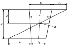
![]()
Fig 6.13 Graphical determination of centroid, CS, of a trapeze
Ch 6 Hull Equipment Ch 6
![]()
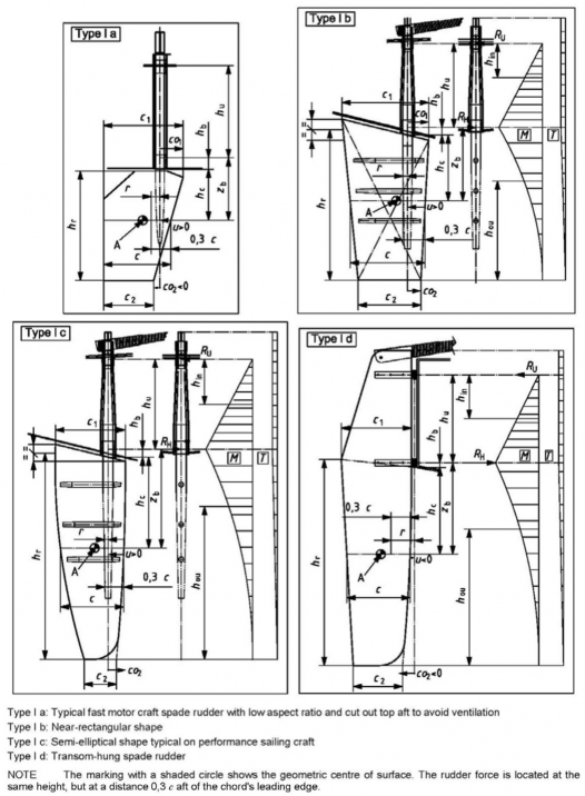
Fig 6.14 Spade rudders: Type I
3. Rudder types II to V (see Fig 6.15)
The dimensions are the same as for spade rudders, except that:
- A is the total area of the moving part of the rudder, divided into AË and AË in Type V;
- AĖ is the skeg area (only used to determine the type in Fig 6.15);
- YZ is the average height of the rudder;
Ch 6 Hull Equipment Ch 6
![]()
Ë
- YZ
Ó G JAŊ
is the effective rudder geometric aspect ratio
where AŊ is the rudder effective area (moving part plus effective part of the skeg, see Table 6.13);
- Ẅ G AŊ ĤYZ is the mean chord;
- YZ is the height of the skeg/horn between hull and mid-skeg bearing for Type V and the lower bearing for Types III and IV.
Table 6.13 gives values of A and AŊ according to rudder type.
Table 6.13 Rudder types and effective areas
Type | Value | |
A | AŊ | |
II | A | |
III | AË | AË Ğ AĖ |
IV | AË | AË |
V | AË Ğ AË | AË Ğ AË Ğ AĖ |
For Type V, YẀ and he are the portions of YZ above and below the skeg bearing, respectively. For Types II to V:
- Ź is, for rudder Types II and IV, the horizontal distance, fore to aft, from the leading edge of the rudder to the stock vertical axis at the height of centroid of rudder area. For rudder Types III and V, Ź is measured aft of the leading edge of the partial or full narrow skeg (see Fig 6.15);
- Z is the horizontal distance between the position of the centroid of rudder area and the rudder's rotational axis and shall not be taken less than Zmin .
The rudders of Types II to V are considered to be held by three bearings (two bearings in-
side the hull and one skeg bearing, see 405. 3 (1))
Ch 6 Hull Equipment Ch 6
![]()
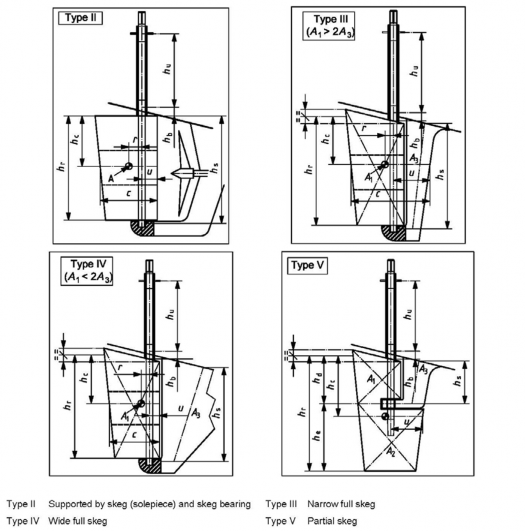
Fig 6.15 Other rudder types: Types II to V
404. Design rudder force calculation
1. General
The design rudder force, Á, shall be taken as follows:
(1) For non-sailing craft, the greater of ÁË and ÁË, defined in 2 and 3, respectively;
(2) For sailing craft, the force ÁË, defined in 2.
2. Force ÁË and corresponding load case
This case corresponds to loads associated with craft handling in the design category sea state.
ÁË G ËĖ × ÄBÄ
× ÝÅÁA
Ë
× ÝÄǼ
× ÝĂAĀ
× ÝÃÅÁ × A
where
ÝÅÁA =
- 1.4 for sailing craft of design categories A and B and non-sailing craft of design category A,
Ch 6 Hull Equipment Ch 6
![]()
- 1.2 for non-sailing craft of design category B,
- 1.0 for craft of design categories C and D;
ÝÄǼ = 6.15 for non-sailing craft of all design categories and sailing craft of design categories C and D;
for sailing craft of design categories A and B, but shall not be taken less than 6.15;
ÄBÄ
ÝÄǼ G JËĤĖ
FŶJËÄŊǼÆËÈF
ÝĂAĀ =
- 1.0 for rudders where the root gap (average clearance between the hull and the rudder root plane) is less than 5 % of the mean rudder chord. This gap shall not be exceeded at any rudder angle,
- 0.85 for rudders which are surface piercing (e.g. transom held) or exceed the gap limitation or can otherwise exhibit significant 3-D flow over the root;
ÝÃÅÁ
= 1 for all craft but may be taken as 0.9 for category C and D sailing craft which are
essentially used for close inshore racing with suitable safety procedures in place and for
which the rudder can be easily inspected on a regular basis. If
ÝÃÅÁ
is taken as 0.9, a
warning requiring regular inspection of rudder(s) should be included in the owner's manual.
3. Force ÁË and corresponding load case
This case corresponds to loads connected with non-sailing craft handling during a turn slight seas. It is therefore only applicable to non-sailing craft.
at speed in
Ë
Á G ĖĒŊ × ÓŊĦĖĖ × ÃÀAB ËĦĖ × ÝĂAĀ × ÝÅÁĄÃ × ÝÁÄAÅ × ÝÅÂĂ × A
where Ó ÃÀAB
ÝĂAĀ
ÝÅÁĄÃ
is the geometric aspect ratio defined in Equation (1) or (7);
is the craft maximum speed in calm water and mLDC conditions; is as given in 807. 2;
=
- 1.0 for design category A and B craft,
- 0.8 for design category C and D craft (may also be taken as 1);
If ÝÅÁĄÃ
= 0.8 is used, a note to this effect should be placed in the owner's manual.
ÝÁÄAÅ G ËĦŊĒ G ŊĦŊŊĒ × ÃÀAB with ŊĦĒÈ ≤ ÝÁÄAÅ Ĥ Ë ÝÅÂĂ G ËĦËÈ
405. Rudder bending moment and reactions at bearings
1. Spade rudder (Type I)
(1) Values of ÝẄ, bending moment À and reactions at bearings for spade rudders (Type I)
ÀĂ G Á × aẄ
is the design rudder bending moment (at hull bearing) for spade rudders, where
- Á is determined according to 404.;
- aẄ is the bending moment lever for spade rudders (see 403. 1 (1)):
Ch 6 Hull Equipment Ch 6
![]()
aẄ G FÝẄ × YZFĞ YẄ G YẄ Ğ YẄ
where ÝẄ is the rudder bending coefficient, determined according to rudder type, as follows.
To calculate aẄ, one shall first determine the value of YẄ:
- for a trapezoidal or near trapezoidal shape, either
a) use the value of ÝẄ given by Equation in 403. 2. or Table 6.12, or
b) apply the graphical method shown in Fig 6.13 ;
- for other shapes, find
aẄ G YẄ ĞYẄ.
YẄ G ÝẄ × YZ by any geometrical method and then calculate
The reactions at bearings for spade rudders are as follows:
aẄ
ĄÃ G Á JYŹ
is the reaction at the upper bearing (at deck or intermediate level), where YŹ is the vertical distance between the centres of the upper and lower bearings (see Fig 6.14);
ĄĂ G ĄÃ Ğ Á
is the reaction at the hull bearing.
2. Skeg rudders (Types II to V)
(1) General
Rudders supported by a skeg or horn are considered to be held, from bottom to top, by three bearings (see Fig 6.15):
- a skeg bearing, with reaction ĄÅ
- a hull bearing located close to the hull bottom at the rudder level, with reaction ĄĂ
- an upper bearing located at deck level at the rudder level or an intermediate level between
hull and deck, with reaction ĄÃ.
(2) Methods of calculation
Rudders of Types II to V may be analysed by one of the following methods:
- continuous beam theory (also known as the three-moment equation) or the method in ISO 12215-8 Annex C;
- the simplified method of 405. 3 (4).
(3) Continuous beam theory See ISO 12215-8.
(4) Simplified method
See ISO 12215-8.
406. Rudder design torque, Å
Å G Á ×Z is the rudder design torque where
Á is as defined in 404. ;
Z is the rudder torque arm but shall not be taken less than Zmin , as defined in Table 6.14.
Ch 6 Hull Equipment Ch 6
![]()
Type | Z | Zmin |
I | ŊĦĖẄGŹ | ŊĦËẄ |
II | ŊĦĖẄGŹ | ŊĦËẄ |
III | ŊĦÈẄGŹ | ŊĦŊÈ Ẅ |
IV | ŊĦËÈẄGŹ | ŊĦŊÈ Ẅ |
YẀ Z | ||
NOTE Ẅ and Ź are defined in 403. | ||
Table 6.14 Values of Z and
Zmin
according to rudder type
YẀ ZF Ẅ
407. Rudder and rudder stock design See ISO 12215-8.
408. Clearance between stock and bearings
Where the bushing manufacturer specifies the necessary clearance between stock and bushing, this shall be adopted. In the absence of such information, the following equations may be used. Table
6.15 gives pre-calculated values for these equations.
J
ǼGẀ G
ËĦÈ× Ẁ Ğ ŊĦË Ğ water soaking expansion, in millimetres, is the minimum recommended
ËŊŊŊ
value.
Ė× Ẁ
ǼGẀ G JËŊŊŊ Ğ ŊĦË Ğ water soaking expansion, in millimetres, is the maximum recommended value.
Table 6.15 Computed recommended values of diametric clearance Ǽ G Ẁ between stock and bushing
Dimensions in millimetres
Stock outer diameter Ẁ | Diametric clearance Ǽ G Ẁ | |
min. | max. | |
40 | 0.16 | 0.32 |
60 | 0.19 | 0.38 |
80 | 0.22 | 0.44 |
100 | 0.25 | 0.50 |
120 | 0.28 | 0.56 |
140 | 0.31 | 0.62 |
160 | 0.34 | 0.68 |
180 | 0.37 | 0.74 |
200 | 0.40 | 0.80 |
Ch 6 Hull Equipment Ch 6
![]()