Iranian Classification Society Rules

< Previous | Contents | Next >
Section 4 Cargo Containment
401.
General
1. In addition to the definitions in 106., the definitions given in this Section apply throughout this Guidance.
402.
Definitions
1. Cargo tank
(1) Cargo tanks are to be of independent tank. Independent tanks are self-supporting; they do not form part of the ship's hull and are not essential to the hull strength.
(2) Cargo tank is all pressurized equipment up to the cargo tank first stop valve of a cargo con- tainment system that stores compressed gas within cargo holds. Cargo tank includes the storage
container and associated cargo tank piping up to first stop valve. Cargo tanks can be either
coiled type or multiple cylinder type, as defined below:
(A) "Coiled cargo tank" is a cargo tank composed of long continuous coiled pipe inside the cargo hold supported independently, and include a cargo tank piping up to first stop valve.
(B) "Cylinderical cargo tank" is a cargo tank composed of an assembly of multiple individual cargo cylinders connected by a common manifold and supported individually inside the car-
go hold, and include a cargo tank piping up to first stop valve.
(C) "Cargo cylinder" is an individual pressure vessel for storage of CNG.
(D) "Cargo tank piping" is the piping manifolds connecting main pressurized components of the cargo tank and the cargo tank first stop valve. Cargo tank piping is within the cargo hold and there should be no valve or flow-restricting devices.
(E) "Cargo tank first stop valve" is the valve isolates the cargo tank from the cargo piping.
(3) There are three categories of cargo tanks according to their materials.
(A) Full metallic cargo tanks
(B) Full composite cargo tanks
(C) Cargo tanks composed of combination of metallic and non-metallic materials
(4) Novel technology other than mentioned above may be accepted with special consideration of this Society on a case-by-case.
2. Design pressure
(1) The design pressure P0 is the maximum gauge pressure at the top of the tank which has been used in the design of the tank.
(2)
For cargo tanks, where there is no temperature control and where the pressure of the cargo is dictated only by the ambient temperature, P0 is not to be less than the gauge pressure of the
cargo at a temperature of 45℃. However, lesser values of this temperature may be accepted by
the Society for ships operating in restricted areas or on voyages of restricted duration and ac-
count may be taken in such cases of any insulation of the tanks. Conversely, higher values of
this temperature may be required for ships permanently operating in areas of high ambient temperature.
(3) In all cases, P0 is not to be less than MARVS.
3. Maximium Allowable Operating Pressure(MAOP)
The Maximum Allowable Operating Pressure (MAOP) is the maximum sustained pressure that is al- lowed during service at coincident fluid/gas temperature. The normal operating pressure is not to exceed the maximum allowable operating pressure. Maximum allowable operating pressure is not to be more than 95 % of the design pressure.
4. Design temperature
The design temperature for selection of materials is the minimum temperature at which cargo may be loaded or transported in the cargo tanks. Provisions to the satisfaction of the Society are to be made to ensure that the tank or cargo temperature cannot be lowered below the design temperature. Also, the expected lower temperatures during accidental events such as blowdown, jet impingement cooling, etc. are to be considered.
![]()
5. Leak before failure(LBF)
Leak Before Failure(LBF) means that unstable fracture will not occur in the cargo tanks from a fa- tigue crack before a possible leak from the calculated through thickness crack is detected and the tank pressure relieved (blown-down)
403.
1.
Design loads
General
(1) Tanks together with their supports and other fixtures are to be designed taking into account proper combinations of the following loads:
· internal pressure
· external pressure
· dynamic loads due to the motions of the ship
· thermal loads
· loads corresponding to ship deflection
· tank and cargo weight with the corresponding reactions in way of supports
· insulation weight
· Loads in way piping connections and other attachments.
· Liquid load, if any (ex, cargo transfer liquid load)
· Cyclic loads
· Accidental loads
· Vibrations
· Residual loads due to fabrication
The extent to which these loads are to be considered depends on the type of tank, and is more fully detailed in the following paragraphs.
(2) Account is to be taken of the loads corresponding to the pressure test referred to in 409.
(3) The tanks are to be designed for the most unfavourable static heel angle within the range 0° to 30° without exceeding allowable stresses given in 405. 1.
(4) Loading rates are be considered for composite materials, since these materials have rate depend- ent properties.
2. Internal pressure
(1) The internal pressure
Peq
resulting from the design pressure P and the liquid pressure
Pgd
de-
fined in (2) are to be calculated as follows:
Peq P Pgd
(MPa)
Equivalent calculation procedures may be applied.
(2) The internal liquid pressures are those created by the cargo transfer liquid where fluid is used for transfer of cargo from the cargo tank. The value of internal liquid pressure Pgd(max) result- ing from combined effects of gravity and dynamic accelerations is to be considered.
· Static fluid pressure head; and
· Dynamic loads resulting from the acceleration of center of gravity of the cargo due to the ship motions
3. External pressure
External design pressure loads are to be based on the difference between the minimum internal pressure (maximum vacuum) and the maximum external pressure to which any portion of the tank may be subjected simultaneously.
4. Dynamic loads due to ship motion
(1) The determination of dynamic loads is to take account of the long-term distribution of ship mo- tions, including the effects of surge, sway, heave, roll, pitch and yaw on irregular seas which the ship will experience during its operating life (normally taken to correspond to wave en- counters). Account may be taken of reduction in dynamic loads due to necessary speed reduc- tion and variation of heading when this consideration has also formed part of the hull strength assessment.
(2) For design against plastic deformation and buckling the dynamic loads are to be taken as the
![]()
most probable largest loads the ship will encounter during its operating life (normally taken to correspond to a probability level of ). Formulae for acceleration components are given in 412.
(3) When design against fatigue is to be considered, the dynamic spectrums are to be determined by long-term distribution calculation based on the operating life of the ship (normally taken to
correspond to wave encounters). If simplified dynamic loading spectra are used for the esti- mation of the fatigue life, those are to be specially considered by the Society.
(4) Ships for restricted service may be given special consideration.
(5) The accelerations acting on tanks are estimated at their centre of gravity and include the follow-
ing components:
· vertical acceleration: motion accelerations of heave, pitch and, possibly, roll (normal to the ship base);
· transverse acceleration: motion accelerations of sway, yaw and roll; and gravity component of roll;
· longitudinal acceleration: motion accelerations of surge and pitch; and gravity component of
pitch.
5. Thmal loads
(1) Tcarragnosietenmt ptheerarmtuarel slobaedlos wdu-r5in5g℃c. ooling down periods are to be considered for tanks intended for
(2) Stationary thermal loads are to be considered for tanks where design supporting arrangements and operating temperature may give rise to significant thermal stresses.
Loads on supports
6.
404.
1.
The loads on supports are covered by 406.
Structural analyses
General
(1) The designs and constructions of cargo tanks are to comply with this Guidace or relevant Recognised Codes/Standards acceptable to this Society such as ASME B&PV Codes, Code Case 2390 "Composite Reinforced Pressure Vessels (CRPV)", BS 5500, CODAP, ANSI B31.3, etc. The applicability of Codes/Standards to sea going containment system is to be demonstrated. Subject to special consideration by the Society, requirements of these Codes/Standards may be modified to take into account specificities of the proposed design. However, materials are to be in compliance with Sec.6.
(2) Where a certain aspect of the design is not in full compliance with this Guidance or a relevant Recognised Codes/Standards acceptable to this Society, the specific variations are to be advised and justified and will be reviewed by this Society on a case-by-case basis. As an alternative, a probabilistic limit state approach design can be acceptable.
(3) Cargo tanks are to be designed using model tests, refined analytical tools and analysis methods to determine stress levels, fatigue life and crack propagation characteristics.
(4) The effects of all dynamic and static loads are to be used to determine the suitability of the
structure with respect to:
· yielding strength
· buckling
· fatigue failure
· crack propagation
Statistical wave load analysis in accordance with 403. 4., finite element analysis or similar
methods and fracture mechanics analysis or an equivalent approach, are to be carried out.
(5) A three-dimensional analysis is to be carried out to evaluate the stress levels contributed by the ship's hull. The model for this analysis is to include the cargo tank with its supporting and keying system as well as a reasonable part of the hull.
(6) A complete analysis of the particular ship accelerations and motions in irregular waves and of the response of the ship and its cargo tanks to these forces and motions are to be performed unless these data are available from similar ships.
(7) A buckling analysis is to consider the maximum construction tolerances.
(8) Where deemed necessary by the Society, model tests may be required to determine stress con-
centration factors and fatigue life of structural elements.
![]()
2. Scantlings based on pressure
(1) Scantlings based on internal pressure are to be calculated as follows:
(A) The thickness and form of pressure-containing parts of pressure vessels under internal pres- sure, including flanges are to be determined according to the requirements for Class 1 pres-
sure vessels of Pt 5, Ch 5 of the Rules or recognized pressure vessel codes such as
ASME, etc, acceptable to the Society. These calculations in all cases are to be based on
generally accepted pressure vessel design theory. Openings in pressure-containing parts of pressure vessels are to be reinforced in accordance with the requirements of Pt 5, Ch 5 of
the Rules or recognized pressure vessel codes acceptable to the Society.
(B) The design internal pressures defined in 403. 2. are to be taken into account in the above
(A) calculations.
(C) The welded joint efficiency factor to be used in the calculation according to (A) is to be
0.95 when the inspection and the non-destructive testing referred to in 409. 5. are carried out. This figure may be increased up to 1.0 when account is taken of other considerations, such as the material used, type of joints, welding procedure and type of loading. For special
materials, the above-mentioned factors are to be reduced depending on the specified mechan-
ical properties of the welded joint.
(2) Buckling criteria are to be as follows:
(A) The thickness and form of pressure vessels subject to external pressure and other loads causing compressive stresses are to be to a recognized pressure vessel code, such as KS,
ASME, etc, acceptable to the Society. These calculations in all cases are to be based on generally accepted pressure vessel buckling theory and are to adequately account for the dif-
ference in theoretical and actual buckling stress as a result of plate edge misalignment, oval- ity and deviation from true circular form over a specified arc or chord length.
(B) The design external pressure Pe used for verifying the buckling of the pressure vessels is
not to be less than that given by:
Pe P P P
Where:
(MPa)
P setting value of vacuum relief valves. For vessels not fitted with vacuum relief valves P are to be specially considered, but is not in general to be taken as less than 0.025 MPa.
P the set pressure of the pressure relief valves for completely closed spaces contain- ing pressure vessels or parts of pressure vessels; elsewhere P = 0.
P compressive actions in the shell due to the weight and contraction of insulation,
weight of shell, including corrosion pressure loads to which the pressure are not limited to, weight of piping,
allowance, and other miscellaneous external vessel may be subjected. These include, but accelerations and hull deflection. In addition
the local effect of external or internal pressure or both are to be taken into account.
P external pressure due to head of water for pressure vessels or part of pressure vessels on exposed decks; elsewhere P = 0.
(3) Stress analysis in respect of static and dynamic loads is to be performed as follows:
(A) Pressure vessel scantlings are to be determined in accordance with (1) and (2).
(B) Calculations of the loads and stresses in way
of the supports and the shell attachment of
the support are to be made. Loads referred to in 403. are to be used, as applicable.
Stresses in way of the supports are to be to a
standard acceptable to the Society. In special
cases a fatigue analysis may be required by the Society.
(C) If required by the Society, secondary stresses and thermal stresses are to be specially considered.
(4) For pressure vessels, the thickness calculated according to (1) or the thickness required by (2)
![]()
plus the corrosion allowance, if any, are to be considered as a minimum without any negative tolerance.
3. Fatigue evaluation
(1) General
The cargo tank is to be subject to fatigue analysis, considering all fatigue loads and their ap- propriate combinations for the life of the cargo tanks. Design S-N curves used in the analysis are to be applicable to the materials and weldments, construction details, fabrication procedures and applicable state of the stress envisioned. Fatigue testing of the cargo tank is required to validate S-N curve analysis.
The cumulative effect of the fatigue load is to comply with:
≤
Where:
= number of stress cycles at each stress level during the life of the ship
= number of load cycles due to loading and unloading during the life of the ship
= number of cycles to fracture for the respective stress level according to the Wöhler (S-N) curve
= number of cycles to fracture for the fatigue loads due to loading and unloading
≤ 0.1
The cumulative fatigue damage due to loads, as defined in 403., is not to exceed 0.1(Safety factor is 10). In this case, the minimum design life of a ship is not to be less than 20 years. When model tests are required to establish S-N curve, the characteristic S-N curve for use in design is defined as the "mean-minus-three standard deviations" curve obtained from a log
S- log N experimental data. With a Gaussian assumption for the residuals in log N with respect to the mean curve through the data, this corresponds to a curve with 99.865 % survival probability. The uncertainty in this curve when its derivation is based on a limited number of test data is to be accounted for. It is required that the characteristic curve be estimated with at least 95 % confidence. When a total of n observations of the number of cycles to failure N are available from n fatigue tests carried out at the same representative stress range S, then the characteristic value of log N at this stress level is to be taken as:
log log
Where:
lo is the mean value of the n observed values of log N and,
· log is the standard deviation of the n observed values of log N and c is a
factor
![]()
Number of observation, n | Factor c |
3 | 13.7 |
5 | 7.29 |
10 | 5.05 |
15 | 4.45 |
20 | 4.19 |
30 | 3.91 |
50 | 3.66 |
100 | 3.44 |
∞ | 3.00 |
(2) If simplified dynamic loading spectra are used for the estimation of the fatigue life in accord- ance with the requirements in 403. 4 (3), the stress due to fatigue load may be generally de- termined by using the cumulative probability curve as shown in following figure.
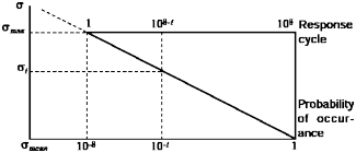
In this case, the number of representative stress( ) is to be eight, and and repetition may be obtained from the following equation :
its number of
ma
Where,
i = 1, 2, 3, ......, 8
ma : stress induced by the predicted maximum dynamic load (half amplitude)
4. Fracture mechanics evaluation
Fatigue analysis using fracture mechanics crack propagation calculations is to be carried out for the cargo tank. The analysis may be carried out in accordance with ASME B & PV Code, API 579 or BS 7910 guidelines, etc. The analysis is to assume crack-like defects located in parent metal, weld
metal and HAZ. The assumed initial defect size in the analysis is to reflect tivity limit.
guaranteed NDT sensi-
(1) The following requirements are to be satisfied for the validity of the design. The calculated number of design load cycles is to be computed based on an allowable assumed initial surface
flaw size (with minimum depth-to-length ratio of 1:3) grown under all
fatigue loads and their
appropriate combinations to that of an allowable final crack depth relative to critical crack depth and wall thickness of the material. Critical crack depth for a given loading condition is defined as: the crack depth at which the stress intensity becomes equal to material toughness value, KIC,
i.e., onset of unstable crack growth occurs.
![]()
The calculated number of design load cycles is to be taken as the lesser of the following:
(A) The number of cycles corresponding to one-half the number of cycles required to propagate a crack from the initial assumed flaw size to the theoretical critical crack depth.
(B) The number of cycles required to propagate a crack from the initial assumed flaw size to a depth equal to 25 % of the theoretical critical crack or 25 % of wall thickness, whichever is
smaller.
(2) Only in the case of coiled type cargo containment system, if the above requirement in (1) is not demonstrated by analysis, then experimental demonstration of three times the design number of cycles by actual prototype testing is to be acceptable.
(3) In the above analysis, as per (1), ductile failure mode is mandatory and is to be demonstrated during prototype testing of the cargo cylinder/cargo tank as given in 410. In ductile failure mode, no physical separation of material into fragments is expected. Whenever small fragments are observed during prototype testing, scanning electron microscopic examination of fractured surfaces is to be carried out to demonstrate complete ductile failure mode at the microstructural level at service and JT temperatures.
(4) Leak Before Failure(LBF) Condition
If the required number of load cycles for the crack to propagate through the wall thickness re- quired in (1) cannot be demonstrated, it is to be documented that unstable fracture will not oc- cur in the cylinder from a fatigue crack before a possible leak from the calculated through
thickness crack is detected and the tank pressure relieved (blown-down).
(5) When LBF design criterion is not demonstrated in the design analysis, provision for monitoring subcritical crack growth in the cargo tanks is required. The full scheme of monitoring subcritical
crack growth must be submitted to this Society for review and approval, prior to application of
this paragraph. The consequence of failure will form the basis for the extent of monitoring required.
(6) Fracture Toughness Data
Whenever fracture toughness data (such as KIC, JIaCnd CTOD) are used in the design analysis, these are to be experimentally determined for the materials and weldments at appropriate service
temperatures and temperature ranges to establish a ductile-brittle transition zone.
(7) Fatigue Crack Growth Data
When required, fatigue crack growth data used in the design analysis are to be generated ex- perimentally based on mean plus 2 standard deviation values for the crack propagation data.
405.
1.
Allowable stresses and corrosion allowances
Allowable stress
(1) Where cargo tanks are designed based on recognized pressure vessel codes, the allowable stress criteria are to be complied with the codes. The cargo tank is to be prototype tested for ver- ification of design and pressure integrity as required by 410.
(2) For cargo tanks designed using the probabilistic limit state approach, the design will be eval- uated by this Society on a case-by-case basis.
(3) Provisions, which are not mentioned here, such as fatigue, crack propagation, etc, are to be
complied with the relevant requirements in this Guidance.
(4) For cargo tanks designed using the new technology, the design criteria is this Society on a case-by-case basis.
(5) Stresses up to 90 % of the yield stress are permissible during hydrostatic
portation, installation and commissioning of the cargo tanks.
(6) The allowable stresses of cargo tanks are not to exceed:
to be considered by
test, handling, trans-
≤
≤
≤
≤
where:
= equivalent primary general membrane stress
![]()
= equivalent primary local membrane stress
= equivalent primary bending stress
= the lesser of or
= the lesser of or
With and as defined in (7), with regard to the stresses , and see also the defi- nition of stress categories in 413. The values A, B, C and D are to have at least the follow- ing minimum values:
Nickel steels and carbon-manganese steels | Austenitic Steels | Alumimum Alloys | |
A | 3 | 3.5 | 4 |
B | 2 | 1.6 | 1.5 |
C | 3 | 3 | 3 |
D | 1.5 | 1.5 | 1.5 |
(7) For the purpose of (6), the following apply:
(A) = specified minimum yield stress at room temperature (N mm ). If the stress-strain curve does not show a defined yield stress, the 0.2 % proof stress applies.
= specified minimum tensile strength at room temperature (N mm ).
For welded connections in aluminium alloys the respective values of or in annealed conditions are to be used.
(B) The above properties are to correspond to the minimum specified mechanical properties of
the material, including the weld metal in the as-fabricated condition. Subject to special con-
sideration by the Society, account may be taken of enhanced yield stress and
strength at low temperature.
(8) The equivalent stress (von Mises, Huber) are to be determined
tensile
where:
= total normal stress in -direction
= total normal stress in -direction
= total shear stress in - plane.
(9) When the static and dynamic stresses are calculated separately and unless other methods of cal- culation are justified, the total stresses is to be calculated according to:
± , ± , ±
(10)
where:
, and = static stresses
, and = dynamic stresses
all determined separately from acceleration components and hull strain components deflection and torsion.
Allowable stresses for materials other than those covered by Sec 6 are to be subject
proval by the Society in each case.
due to
to ap-
(11) Stresses may be further limited by fatigue analysis, crack propagation analysis and buckling criteria.
![]()
2. Corrosion allowances
(1) No corrosion allowance is to be generally required in addition to the thickness resulting from the structural analysis. However, where there is no environmental control around the cargo tank, such as inerting, or where stress corrosion cracking and corrosion fatigue occurs on the materi- als, the Society may require a suitable corrosion allowance.
(2) No corrosion allowance is generally required if the external surface is protected by inert atmos-
phere or by an appropriate insulation with an approved vapour barrier. Paint or other thin coat- ings are not to be credited as protection. Where special alloys are used with acceptable corro- sion resistance, no corrosion allowance is to be required. If the above conditions are not sat- isfied, the scantlings calculated according to 404. 6. are to be increased as appropriate.
(3) When the cargo tank is designed with no additional corrosion margin, means of thickness mon- itoring is to be provided to confirm that there is no corrosion during the service life of the
ship.
406.
Supports
1. Cargo tanks are to be supported by the hull in a manner which will prevent bodily movement of the tank under static and dynamic loads while allowing contraction and expansion of the tank under temperature variations and hull deflections without undue stressing of the tank and of the hull.
2. The tanks with supports are also to be designed for a static angle of heel of 30° without exceed- ing allowable stresses given in 405. 1.
3. The supports are to be calculated for the most probable largest resulting acceleration, taking into account rotational as well as translational effects.
4. Suitable supports are to be provided to withstand a collision force acting on the tank corresponding to one half the weight of the tank and cargo in the forward direction and one quarter the weight of the tank and cargo in the aft direction without deformation likely to endanger the tank structure.
5. The loads mentioned in Pars 2 and 4 need not be combined with each other or with wave-in- duced loads.
6. Provision are to be made to key the tanks against the rotational effects referred to in Par 3.
7. Anti-flotation arrangements are to be provided. The antiflotation arrangements are to be suitable to withstand an upward force caused by an empty tank in a hold space flooded to the summer load draught of the ship, without plastic deformation likely to endanger the hull structure.
8. The tank support structures are to be arranged to distribute the forces from the cargo tank to the hull primary supporting structures effectively for reducing the stress concentrations.
9. The Fatigue evaluation for supports is to be carried out. However, may be taken as
407.
1.
Insulation
Where a product is carried at a temperature below -10℃ suitable insulation are to be provided to ensure that the temperature of the hull structure does not fall below the minimum allowable design tamnkpseraarteureat gtihveeinr dinesiSgenc 6temfoprertahteurgeraadned otfhestaemelbcieontceternmepde, ratsurdestaailre 5i℃n 4f0o8r., awirhaendth0e℃cafrogro seawater. These conditions may generally be used for world-wide service. However, higher values of the ambient temperatures may be accepted by the Society for ships operated in restricted areas. Conversely, lesser values of the ambient temperatures may be fixed by the Society for ships trading
occasionally or regularly to areas in latitudes where such the winter months.
lower temperatures are expected during
2. Calculations are to be made with the assumptions in Par 1 to check that the temperature of the hull structure does not fall below the minimum allowable design temperature given in Sec 6 for the grade of steel concerned, as detailed in 408.
3. Calculations required by Pars 1 and 2 are to be made assuming still air and still water, and ex- cept as permitted by Par 4, no credit are to be given for means of heating. In the case referred to
in Par 2, the cooling effect of the leaking cargo studies. For structural members connecting inner and
is to be considered in the heat transmission outer hulls, the mean temperature may be tak-
![]()
en for determining the steel grade.
4. In all cases referred to in Pars 1 and 2 and for ambient temperature conditions of 5°C for air and 0°C for seawater, approved means of heating transverse hull structural material may be used to en- sure that the temperatures of this material do not fall below the minimum allowable values. If low- er ambient temperatures are specified, approved means of heating may also be used for longitudinal hull structural material, provided this material remains suitable for the temperature conditions of 5°C for air and 0°C for seawater without heating. Such means of heating should comply with the following requirements:
(1) sufficient heat should be available to maintain the hull structure above the minimum allowable temperature in the conditions referred to in Pars 1 and 2;
(2) the heating system should be so arranged that, in the event of a failure in any part of the sys- tem, stand-by heating could be maintained equal to not less than 100 % of the theoretical heat
load;
(3) the heating system should be considered as an essential auxiliary; and
(4) the design and construction of the heating system should be to the satisfaction of the Society.
5. Where
a hull heating system complying with Par 4 is installed, this system is to be contained
solely within the cargo area or the drain returns from the hull heating coils in the wing tanks, cof-
ferdams and double bottom are to be led to a degassing tank. The degassing tank is to be located in the cargo area and the vent outlets are to be located in a safe position and fitted with a flame screen.
6. In determining the insulation thickness, due regard are to be paid to the cooling system on board.
408.
Materials
1. The shell and deck plating of the ship and all stiffeners attached thereto are to be in accordance with the requirements of Pt 3 of the Rules, unless the calculated temperature of the material in the design condition is below -5°C due to the effect of the low temperature cargo, in which case the material is to be in accordance with Table 3.6.5 assuming the ambient sea and air temperature of 0°C and 5°C respectively.
2. Materials used in the construction of cargo tanks are or 3.6.3.
3. Materials other than those referred to in Pars 1 and
to be in accordance with Table 3.6.1, 3.6.2
2 used in the construction of the ship which
are subject to reduced temperature due to the cargo and which do not form part of the secondary
barrier should be in accordance with Table 3.6.5 for temperatures as determined by 407. This in- cludes inner bottom plating, longitudinal bulkhead plating, transverse bulkhead plating, floors, webs, stringers and all attached stiffening members.
4. The insulation materials are to be suitable for loads which may be imposed on them by the ad- jacent structure.
5. Where applicable, due to location or environmental conditions, insulation materials are to have suit- able properties of resistance to fire and flame spread and are to be adequately protected against penetration of water vapour and mechanical damage.
6. Tests of materials used for thermal insulation
(1) Materials used for thermal insulation are to be tested for the following properties as applicable, to ensure that they are adequate for the intended service:
(A) compatibility with the cargo
(B) absorption of the cargo
(C) shrinkage
(D) ageing
(E) closed cell content
(F) density
(G) mechanical properties
(H) thermal expansion
(I) abrasion
(J) cohesion
(K) thermal conductivity
![]()
(L) resistance to vibrations
(M) resistance to fire and flame spread.
(2) The above properties, where applicable, are to be tested for the range between the expected maximum temperature in service and 5°C below the minimum design temperature.
7. The procedure for fabrication, storage, handling, erection, quality control and control against harmful exposure to sunlight of insulation materials are to be to the satisfaction of the Society. "The sat- isfaction of the Society" means as shown in the following (1) and (2):
(1) The insulation materials are to be approved in accordance with the Guidance. In the above, tests and inspection are to be conducted according to the procedures on the manufacture, stor- age, handling and product quality control established by the manufacturer.
(2) The inspection for insulation work is to include the following items of tests and inspections (A) to (C):
(A) Insulation procedure test
For insulation system and insulation procedure without previous records, tests are to be con- ducted in accordance with the test plan approved by the Society. The test may be conducted at the manufacturer of insulation materials or shipyard as necessary.
(B) Insulation production test
In accordance with the test plan approved by the Society in advance, tests are to be con-
ducted to verify the work control, working environment control and product quality control during insulation procedure.
(C) Completion inspection
After the insulation work is completed, inspection is to be conducted for dimensions, shape, appearance, etc. in accordance with the procedures already approved by the Society, and in addition, the insulation performance is also to be verified in the test specified in 409. 9.
8. Where powder or granulated insulation is used, the arrangements are to be such as to prevent com- pacting of the material due to vibrations. The design is to incorporate means to ensure that the material remains sufficiently buoyant to maintain the required thermal conductivity and also prevent any undue increase of pressure on the cargo containment system.
9. Composite materials
Cargo tanks designed with composite materials are to be specially considered and are to be de- signed and constructed in accordance with the requirements of the recognized Standards acceptable to the Society. However, the Society may request additional requirements in addition to the stand- ards mentioned above, if deemed necessary.
10. Insulation material characteristics
(1) The materials for insulation are to be approved by the Society.
(2) The approval of bonding materials, sealing materials, lining constituting a vapour barrier or me- chanical protection is to be considered by the Society on a case-by-case basis. In any event, these materials are to be chemically compatible with the insulation material.
(3) Before applying the insulation, the surfaces of the tank structures or of the hull are to be care- fully cleaned.
(4) Where applicable, the insulation system is to be suitable to be visually examined at least on
one side.
(5) When the insulation is sprayed or foamed, the minimum steel temperature at the time of appli- cation is to be not less than the temperature given in the specification of the insulation.
409.
Construction and testing
1. All welded joints of the shells of cargo tanks are to be of the butt weld, full penetration type.
Nozzle welds are also generally to be designed with full penetration.
2. Welding joint details for cargo tanks are to be as follows:
(1) All longitudinal and circumferential joints of cargo tanks are to be of butt welded, full pene- tration type. The butt weld joints are generally to be made without backing material. When per- mitted, the backing material is to be removed and the root profile is to be ground and exam- ined for acceptance.
(2) All welds connecting heads, nozzles or other penetrations into the cargo tank are to be full pen- etration welds extending through the entire thickness of the cargo tank wall or nozzle wall, un-
![]()
less specially approved by the Society for small connections.
(3) The bevel preparation of the welded joints is to be designed in accordance with a pressure ves- sels code acceptable to the Society.
(4) The finished weld is to be ground or machined to blend with the surfaces of the parts being joined. Both the blend radii and the surface finish of the weld deposit are to be inspected to
ensure they comply with the design requirements. When grinding is not carried out, the joint
design is to be justified by analysis and testing, and is to be reviewed and approved by the Society.
(5) When pipes are used for cargo tanks fabrication, the manufacturing, testing and inspection of
the pipes are to be in accordance with Sec 5.
3. Workmanship is to be to the satisfaction of the Society.
4. A quality control specification including maximum permissible size of constructional defects, tests and inspections during the fabrication, installation and also sampling tests at each of these stages are to be to the satisfaction of the Society.
5. For cargo tanks, inspection and non-destructive testing are to be as follows:
(1) Manufacture and workmanship : The tolerances relating to manufacture and workmanship such as out-of-roundness, local deviations from the true form, welded joints alignment and tapering of plates having different thicknesses, are to comply with standards acceptable to the Society. The tolerances are also to be related to the buckling analysis referred to in 404. 2 (2)
(2) Non-destructive testing : The non-destructive testing of weld joints in cargo tanks pressurized parts are not to be less than the following:
Radiography testing: butt welds 100 % Surface crack detection: all welds 100 %.
In addition, the Society may require total ultrasonic testing on welding of reinforcement rings
around holes, nozzles, etc.
6. Pressure testing
Each cargo cylinder/tank is to be pressure tested for final acceptance. In the case of cargo tank, made of composite materials, depending on the material and design, pressure testing procedures are to be developed and submitted for review and may include burst test in addition to pressure testing on a lot basis for acceptance. Whereas, cargo tank is to be subjected to a hydrostatic or hydro- pneumatic test as follows:
(1) Each cargo tank, when completely manufactured, is to be subjected to a hydrostatic test at a pressure measured at the top of the cargo tanks of not less than 1.25 , but in no case during the pressure test is the calculated primary membrane stress to exceed 90 % of the yield stress of the material. To ensure that this condition is satisfied, where calculations indicate that this stress will exceed 75 % of the yield strength, the test is to be monitored by the use of strain gauges or other suitable equipment.
(2) The test pressure is to be increased in increments of no more than 20 % of the test pressure and stabilized before proceeding to the next incremental level. When final test pressure is at- tained, pressure is to be stabilized and held for a minimum of 5 minutes. The pressure is then to be reduced and held at the design pressure to allow for thorough inspection for leaks.
(3) Each individual cargo cylinder may be tested separately and only a tightness test will be re- quired for the full assembly.
(4) Only fluid medium which is noncorrosive to the cargo tank material and liquid at the test pres- sure and temperature are to be used in pressure testing. Care is to be exercised to ensure the
noncorrosive nature of the liquid medium. If required, corrosion inhibitors are to be added.
After the hydrostatic test, cargo tanks are to be inspected to ensure that the fluid medium and other debris are completely removed from the tanks and the tanks are completely dried. In order
to minimize risk of brittle fracture, the test temperature is to be at least 20℃ above the materi-
al impact test temperature.
(5) When specially approved by the Society, pneumatic tests may be carried out on cargo tanks with the conditions as prescribed in (1) and (2). This testing is permitted when cargo tanks are
so designed or supported that they cannot be safely hydrostatically tested
using a liquid
medium. The air or gas medium used during the testing is to be free from moisture, carbon di- oxide and other deleterious contaminants that may cause corrosion in the cargo tank.
(6) After completion and assembly, each cargo containment system and its related fittings are to be subjected to an adequate tightness test.
![]()
(7) After completion of the above pressure testing, cargo tanks are to be filled with inert/non- corrosive medium to avoid any internal corrosion problems and stored in dry/noncorrosive in- erted atmosphere to avoid any external corrosion problems.
7. Cargo tanks are to be protected from internal and external corrosion, abrasion, and physical damage of any kind during storage, transportation, installation and commissioning in the cargo hold.
8. At least one cargo tank per hold and its support are to be instrumented to confirm stress levels and loads, unless the design and arrangement for the size of ship involved are supported by full- scale experience. The cargo tank to be instrumented will be selected on the basis of the stress analysis.
The overall performance of the cargo containment system is to be verified for compliance with the
9. design parameters during the initial loading and discharging of the cargo. Records of the perform- ance of the components and equipment essential to verify the design parameters are to be main-
tained and available to the Society.
10. Heating arrangements, if fitted in accordance with 407. 4, are to be tested for required heat out- put and heat distribution.
11. Where cargo is carried at temperature below ambient, the hull is to be visually inspected for cold spots to the satisfaction of the Surveyor following the first loaded voyage.
12. Any markings of cargo tanks are to be made by methods which do not cause unacceptable local stress raisers.
410. CNG Cargo Tank Prototype Testing
Prototype test is required for all new cargo tank design. The test program is to be submitted to this Society to review the static strength, fatigue and burst performance.
A set of full scale(with respect to diameter, thickness, number of circumferential welds, including
end-caps but not necessarily full length) fatigue and burst tests are to be performed and it must be documented that the cylinder wall, end-caps and welding gas sufficient reliability against fatigue and that the cylinder posses sufficient bust resistance after twice the number of anticipated pressure induced stress cycles. A minimum of 3 tests must be performed. 3 tests are to be of one burst test after having being subjected to twice the anticipated number of stress cycles and 2 fatigue tests to document that the fatigue capacity is in excess of 15 × the number of stress cycles for the cylinders during the design life time.
411.
Stress Relieving for Cargo Tanks
1. Stress relieving of cargo tanks is to be carried out by thermal means.
(1) For cargo tanks of carbon and carbon-manganese steels, post-weld heat treatment is to be per- formed after welding. Post-weld heat treatment in all other cases and for materials other than those mentioned in Sec 6 is to be to the satisfaction of the Society. The soaking temperature and holding time are to be to the satisfaction of the Society.
(2) For TMCP steels, thermal stress relieving operations are generally prohibited unless specially ap- proved by the Society.
2. Where the size of the cargo tanks and/or metallurgical characteristics of materials are adversely af- fected due to thermal treatment (may occur for TMCP Steels), alternative methods of stress reliev- ing will be considered if acknowledged by this Society.
412. Guidance formulae for acceleration components
The following formulae are given as guidance for the components of acceleration due to ship's mo-
tions corresponding to a probability level of in the North Atlantic length exceeding 50 m .
and apply to ships with a
![]()
Vertical acceleration as defined in 403. 4 (5) : ±
![]()
![]()
Transverse acceleration as defined in 403.
4 (5) : ±
Longitudinal acceleration as defined in 403. 4 (5) : ±
with:
where:
= length of the ship for determination of scantlings as defined in Pt 3, Ch 1 of the Rules (m )
= block coefficient as defined in Pt 3, Ch 1 of the Rules
= greatest moulded breadth of the ship as defined in Pt 3, Ch 1 of the Rules (m )
= longitudinal distance (m ) from amidships to the centre of gravity of the tank with contents;
= vertical distance (m ) from the ship's actual water-line to the centre of gravity of tank with contents; is positive above and negative below the waterline.
where: = service speed (knots)
= 1 in general. For particular loading conditions and hull forms, determination of according to the formula below may be necessary.
= 13
where ≥ 1.0 and = metacentric height (m )
, and = maximum dimensionless accelerations (i.e. relative to the acceleration of gravity) in the respective directions and they are considered as acting separately for calculation purposes.
does not include the component due to the static weight, includes the component due to the static weight in the transverse direction due to rolling and includes the component due
413. Stress categories
For the purpose of stress evaluation referred to in 405. 1 (6), stress categories are defined in this Article.
1. Normall stress is the component of stress normal to the plane of reference.
2. Membrane stress is the component of normal stress which is uniformly distributed and equal to the average value of the stress across the thickness of the section under consideration.
3. Bending stress is the variable stress across the thickness of the section under consideration, after the subtraction of the membrane stress.
4. Shear stress is the component of the stress acting in the plane of reference.
5. Primary stress is a stress produced by the imposed loading and which is necessary to balance the
![]()
external forces and moments. The basic characteristic of a primary stress is that it is not self- limiting. Primary stresses which considerably exceed the yield strength will result in failure or at least in gross deformations.
6. Primary general membrane stress is a primary membrane stress which is so distributed in the struc- ture that no redistribution of load occurs as a result of yielding.
7. Primary local membrane stress arises where a membrane stress produced by pressure or other me- chanical loading and associated with a primary or a discontinuity effect produces excessive dis- tortion in the transfer of loads for other portions of the structure. Such a stress is classified as a primary local membrane stress although it has some characteristics of a secondary stress. A stress region may be considered as local if :
≤
where:
= distance in the meridional direction over which the equivalent stress exceeds 1.1
= distance in the meridional direction to another region where the limits for primary general membrane stress are exceeded
= mean radius of the vessel
= wall thickness of the vessel at the location where the primary general membrane stress limit is exceeded
= allowable primary general membrane stress.
8. Secondary stress is a normal stress or shear stress developed by constraints of adjacent parts or by self constraint of a structure. The basic characteristic of a secondary stress is that it is self-limiting. Local yielding and minor distortions can satisfy the conditions which cause the stress to occur.
![]()