Iranian Classification Society Rules

< Previous | Contents | Next >
Section 3 Ship Arrangements
301.
Segregation of the cargo area
1. Hold spaces are to be segregated from machinery and boiler spaces, accommodation spaces, service spaces and control stations, chain lockers, drinking and domestic water tanks and from stores. Hold spaces are to be located forward of machinery spaces of category A, other than those deemed nec- essary by the Society for the safety or navigation of the ship. Bow thrusters are allowed to be fit- ted forward of the hold spaces.
2. Segregation of hold spaces from spaces referred to in Par 1 or spaces either below or outboard of the hold spaces may be effected by cofferdams, fuel oil tanks. A gastight A-0 class division is sat-
isfactory if there is no source of ignition or fire hazard in the adjoining
spaces. Here, "if there is
no source of ignition or fire hazard" means those compartments such as ballast tanks, fresh water tanks, cofferdams, fuel oil tanks, cargo service spaces where there is no source of ignition and is not normally entered by persons, cargo handling system rooms, etc.
3. Hold spaces are to be segregated from the sea by double hull construction with double bottom and double sides.
4. Any piping system which may contain cargo:
(1) is to be segregated from other piping systems, except where inter-connections are required cargo- related operations such as purging, gas-freeing or inerting. In such cases, precautions to be taken to ensure that cargo cannot enter such other piping systems through the ter- connections.
for are in-
(2) except as provided for a fuel gas system in Sec 15, is not to pass through any accommodation
space, service space or control station or through a machinery space other than a cargo handling machinery room.
(3) except for bow/stern and turret loading/unloading arrangements in accordance with 308. and ex-
cept as provided for fuel gas systems in Sec 15, is to be located in the cargo area above the open deck; and
(4) except for athwartship shore connection piping not subject to internal pressure at sea, is to be located inboard of the transverse tank location requirements of 206. 1.
5. Any emergency cargo blow down piping system is to comply with Par 4 as appropriate and may be led aft externally to accommodation spaces, service spaces or control stations or machinery spaces, but is not to pass through them. The location of the cold vent or flare outlet is to be sub- ject to a gas dispersion, a flare radiation and a noise analysis as appropriate in a recognized standard.
6. Arrangements are to be made for sealing the weather decks in way of openings for cargo contain- ment systems and hold spaces.
7. Further total cargo volume stored in each hold space is to be subdivided by providing multiple car- go tanks in a hold space. Each cargo tank volume must not exceed the relieving capacity of relief valves for blow down, normal operation, emergency operation and accidental events as specified in this Guidance.
302.
Accommodation, service and machinery spaces and control stations
1. No accommodation space, service space or control station is to be located within the cargo area.
The bulkheads of accommodation spaces, service spaces or control stations which face the cargo
area are to be so located as to avoid the entry of gas from the hold space to such spaces through a single failure of a deck or bulkhead.
"To be so located as to avoid the entry of gas from the hold space to such spaces through a sin- gle failure of a deck or bulkhead" means that boundaries of the compartment are so arranged as not to make linear contact or point contact with hold spaces. (See Fig 3.3.1)
![]()

Fig 3.3.1
2. In order to guard against the danger of hazardous gas, due consideration are to be given to the lo- cation of air intakes and openings into accommodation, service and machinery spaces and control stations in relation to cargo piping, cargo vent systems and machinery space exhausts from gas burning arrangements. Compliance with the requirements in 302. 4, 308. 4, 802. 7 and 1201. 6 of this Guidance would also ensure compliance with the requirement in this Par, regarding pre- cautions against hazardous gases. Air outlets are subject to the same requirements as air inlets and air intakes.
3. Access through doors, gastight or otherwise, is not to be permitted from a gas-safe space to a gas- dangerous space, except for access to service spaces forward of the cargo area through air-locks as permitted by 306. 1 when accommodation spaces are aft.
4. Entrances, air inlets and openings to accommodation spaces, service spaces, machinery spaces and control stations are not to face the cargo area. They are to be located on the end bulkhead not facing the cargo area or on the outboard side of the superstructure or deck house or on both at a distance of at least 4 % of the length (L) of the ship but not less than 3 m from the end of the superstructure or deck house facing the cargo area. This distance, however, need not exceed 5 m. Windows and sidescuttles facing the cargo area and on the sides of the superstructure of deck house within the distance mentioned above are to be of the fixed (non-opening) type. Wheelhouse windows may be non-fixed and wheelhouse doors may be located within the above limits so long as they are so designed that a rapid and efficient gas and vapour tightening of the wheelhouse can be ensured. Air outlets are subject to the same requirements as air inlets and air intakes.
5. Sidescuttles in the shell below the uppermost continuous deck and in the first tier of the super- structure or deck house are to be of the fixed (non-opening) type.
6. All air intakes and openings into the to be fitted with closing devices. gas-tightness. Ordinary steel fire-flaps
accommodation spaces, service spaces and control stations are The closing devices are to give a reasonable degree of without gaskets/seals are normally not considered satisfactory.
Bolted plates of A60 class for removal of machinery may be accepted on bulkheads facing cargo areas, provided signboards are fitted to warn that these plates may only be opened when the ship
is in gas-free condition.
303.
Cargo handling system rooms
1. Cargo handling system rooms are to be situated above the weather deck and located within the car- go area unless specially approved by the Society. Cargo handling system rooms are to be treated as cargo pump rooms for the purpose of fire protection according to SOLAS regulation II-2/9.2.4. Alternate arrangement is to be specially considered by the Society and details such as Risk Analysis and Fire & Explosion Analysis, etc are to be submitted for review and approval.
2. When cargo handling system rooms are permitted to be fitted above or below the weather deck at the after end of the aftermost hold space or at the forward end of the forwardmost hold space, the limits of the cargo area as defined in 106. 8 are to be extended to include the cargo handling sys- tem rooms for the full breadth and depth of the ship and deck areas above those spaces.
3. Where the limits of the cargo area are extended by Par 2, the bulkhead which separates the cargo
handling system rooms from accommodation spaces of category A are to be so located as single failure of a deck or bulkhead.
and service spaces, control stations and machinery to avoid the entry of gas to these spaces through a
![]()
4. Where handling machinery are driven by shafting passing through a bulkhead or deck, gastight seals with efficient lubrication or other means of ensuring the permanence of the gas seal are to be fitted in way of the bulkhead or deck.
5. Arrangements of cargo handling system rooms are to be such as to ensure safe unrestricted access for personnel wearing protective clothing and breathing apparatus, and in the event of injury to al- low unconscious personnel to be removed. All valves necessary for cargo handling are to be readily accessible to personnel wearing protective clothing. Suitable arrangements are to be made to deal with drainage of cargo handling system rooms.
6. Cargo handling system rooms are not to contain electrical equipment, except as provided for in Sec 10, or other ignition sources such as internal combustion engines or steam engines with oper- ating temperature which could cause ignition or explosion of mixtures of gases, if any, with air.
304.
Cargo control rooms
1. Any cargo control room is to be above the weather deck and may be located in the cargo area.
The cargo control room may be located within the accommodation spaces, service spaces or control
stations provided the following conditions are complied with:
(1) the cargo control room is a gas-safe space; and
(2) if the entrance complies with 302. 4, the control room may have access to the spaces described above;
(3) if the entrance does into comply with 302. 4, the control room is to have no access to the spaces described above and the boundaries to such spaces are to be insulated to A-60 class
integrity.
2. If the cargo control room is designed to be a gas-safe space, instrumentation is to, as far as possi- ble, be by indirect reading systems and is to in any case be designed to prevent any escape of gas into the atmosphere of that space. Location of the gas detector within the cargo control room will not violate the gas-safe space if installed in accordance with 1305. 5.
3. If the cargo control room is a gas-dangerous space, sources of ignition are to be excluded.
Consideration is to be paid to the safety characteristics of any electrical installations.
305.
Access to spaces in the cargo area
1. Visual inspection is to be possible of at least one side of the inner hull structure without the re- moval of any fixed structure or fitting. If such a visual inspection is only possible at the outer face of the inner hull, the inner hull is not to be a fuel-oil tank boundary wall.
2. Inspection of one side of any insulation in hold spaces is to be possible. If the integrity of the in- sulation system can be verified by inspection of the outside of the hold space boundary when tanks are at service temperature, inspection of one side of the insulation in the hold space need not be required.
3. Arrangements for hold spaces, void spaces and other spaces that could be considered gas-dangerous are to be such as to allow entry and inspection of any such space by personnel wearing protective clothing and breathing apparatus and in the event of injury to allow unconscious personnel to be removed from the space and are to comply with the following:
(1) Access is to be provided:
(A) in general and if possible to cargo tanks direct from the open deck;
If there is no access for inspection of each cargo tank from inside due to the design, alter- native means of inspection is to be provided. The documents stating the alternative means
of inspection are to be submitted for approval to this Society. The inspection method from
inside and outside, and the validity of the results are to be included in the documents.
(B) through horizontal openings, hatches or manholes, the dimensions of which are to be suffi- cient to allow a person wearing a breathing apparatus to ascend or descend any ladder with-
out obstruction and also to provide a clear opening to facilitate the hoisting of an injured
person from the bottom of the space; the minimum clear opening is to be not less than 600 mm × 600 mm; and
(C) through vertical openings, or manholes providing passage the space, the minimum clear opening of which is to be
through the length and breadth of not less than 600 mm by 800 mm
![]()
at a height of not more than 600 mm from the bottom plating unless gratings or other foot- holds are provided.
(2) The dimensions referred to in (1) (B) and (C) may be decreased if the ability to traverse such
openings or to remove an injured person can be proved
(3) The requirements of (1) (B) and (C) do not apply to
to the satisfaction of the Society. spaces described in 106. 25 (5). Such
spaces are to be provided only with direct or indirect access from the open weather deck, not
including an enclosed gas-safe space.
4. Access from the open weather deck to gas-safe spaces are to be by means of an airlock in accord- ance with 306.
5. The minimum clearance for inspection required in the requirement of Par 1 and 2 are to be as shown in the Fig 3.3.2.
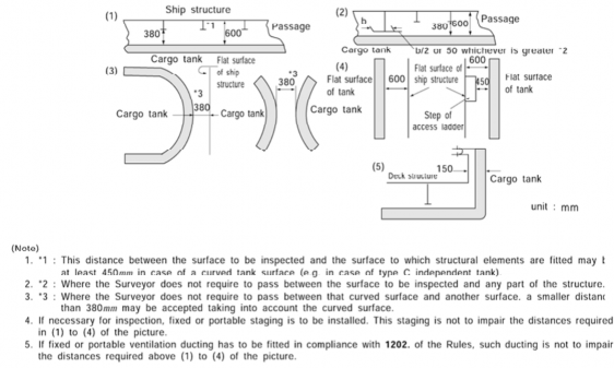
Fig 3.3.2
6. The details of minimum
Fig 3.3.3.
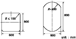
opening size required in 3 (1) (B) and (C) are to be as shown in the
Fig 3.3.3
![]()
306.
Air locks
1. An airlock is to be only permitted between a gas-dangerous zone on the open weather deck and a gas-safe space and is to consist of two steel doors substantially gastight spaced at least 1.5 m but not more than 2.5 m apart.
2. The doors are to be self-closing and without any holding back arrangements.
3. An audible and visual alarm system to give a warning on both sides of the airlock are to be pro- vided to indicate if more than one door is moved from the closed position.
4. Electrical equipment which is not of the certified safe type in spaces protected by airlocks are to be de-energized upon loss of overpressure in the space (see also 1001. 4). Electrical equipment which is not of the certified safe type for maneuvering, anchoring and mooring equipment as well as the emergency fire pumps are not to be located in spaces to be protected by airlocks.
Maintenance of overpressure in spaces protected by air-locks is to be by the differential pressure sensing devices provided within the compartment, but alternatively, either of the following method
(1) or (2) may be employed:
(1) The following means are considered acceptable alternatives to differential pressure sensing de- vices in spaces having a ventilation rate not less than 30 air changes per hour:
(A) Monitoring of current or power in the electrical supply to the ventilation motors; or
(B) Air flow sensors in the ventilation ducts.
(2) In spaces where the ventilation rate is less than 30 air changes per hour, in addition to the (1)
(A) or (B), arrangements are to be made to de-energise electrical equipment which is not of the certified safe type if more than one air-lock door is moved from the closed position.
5. The airlock spaces are to be mechanically ventilated from a gas-safe space and maintained at an overpressure to the gas-dangerous zone on the open weather deck.
6. The airlock spaces are to be monitored for cargo gas.
7. Subject to the requirements of the International Convention on Load Lines in force, the door sill is not to be less than 300 mm in height.
307.
Bilge, ballast and fuel oil arrangements
1. Hold spaces are to be provided with suitable drainage arrangements not connected with the machi- nery space.
2. Ballast spaces, including wet duct keels used as ballast piping, fuel-oil tanks and gas-safe spaces may be connected to pumps in the machinery spaces. Dry duct keels with ballast piping passing through, may be connected to pumps in the machinery spaces, provided the connections are led di- rectly to the pumps and the discharge from the pumps lead directly overboard with no valves or manifolds in either line which could connect the line from the duct keel to lines serving gas-safe spaces. Pump vents are not to be open to machinery spaces.
3. Dry spaces within the cargo area are to be fitted with a bilge or drain arrangement not connected
to the machinery space. Spaces not accessible at arrangements. Spaces without a permanent ventilation
uum relief system or with air pipes.
Bilge arrangements for hold spaces are to be operable
all times are to be fitted with sounding system are to be fitted with a pressure/vac-
from the weather deck.
308.
Bow/stern and turret loading/unloading arrangements
1. Subject to the requirements in 308., cargo piping may be arranged
loading and unloading.
2. Portable arrangements are not to be permitted.
3. In addition to the requirements of Sec 5, the following provisions lated piping equipment:
(1) Cargo piping and related piping equipment outside the cargo
to permit bow, stern or turret
apply to cargo piping and re- area is to have only welded
connections. The piping outside the cargo area is to run on the open least 760 mm inboard except for athwartships shore connection piping.
deck and are to Such piping are
be at
to be
![]()
clearly identified and fitted with a shutoff valve at its connection to the cargo piping system within the cargo area. At this location, it is also to be capable of being separated by means of a removable spool piece and blank flanges when not in use.
(2) The piping is to be full penetration butt welded, and fully radiographed regardless of pipe diam- eter and design temperature. Flange connections in the piping are only permitted within the car- go area and at the shore connection.
(3) Arrangements are to be made to allow such piping to be purged and gas-freed after use. When not in use, the spool pieces are to be removed and the pipe ends be blank-flanged. The vent pipes connected with the purge are to be located in the cargo area.
4. Entrances, air inlets and openings to accommodation spaces, service spaces, machinery spaces and
control stations are not to face the cargo shore connection location
unloading arrangements. They are to be located on the outboard side
of bow or stern loading and
of the superstructure or deck-
house at a distance of at least 4 % of the length of the ship but not less than 3 m from the end
of the superstructure or deck house facing the cargo shore connection location of the bow or stern loading and unloading arrangements. This distance, however, need not exceed 5 m. Sidescuttles fac- ing the shore connection location and on the sides of the superstructure or deckhouse within the distance mentioned above are to be of the fixed (non-opening) type. In addition, during the use of the bow or stern loading and unloading arrangements, all doors, ports and other openings on the
corresponding superstructure or deckhouse side are to be kept closed. Where, in the case of small
ships, compliance with 302. 4 and this paragraph is not possible, the Society may approve relaxa- tions from the above requirements.
5. Deck openings and air inlets to spaces within distances of 10 m from the cargo shore connection location are to be kept closed during the use of bow or stern loading or unloading arrangements.
6. Electrical equipment within a zone of 3 m from the cargo shore connection location are to be in accordance with Sec 10.
7. Fire-fighting arrangements for the bow or stern loading and unloading areas are to be in accordance with 1103. 1 (3) and 1104. 7. Devices to stop cargo handling equipment and to close cargo valves are to be fitted in a position from which it is possible to keep under control the loading/un- loading manifolds.
8. Means of communication between the cargo control station and the shore connection location should be provided and if necessary certified safe.
9. In the case of loading through turret mooring system, the system are to be in compliance with a standards acceptable to this Society.
![]()