Iranian Classification Society Rules

< Previous | Contents | Next >
Section 2 Ship Survival Capability and Location of Cargo Tanks
201. General
Ships subject to this Guidance are to survive the normal effects of flooding following assumed hull damage caused by some external force. In addition, to safeguard the ship and the environment, the cargo tanks are to be protected from penetration in the case of minor damage to the ship resulting, for example, from contact with a jetty or tug, and given a measure of protection from damage in the case of collision or stranding, by locating them at specified minimum distances inboard from the ship's shell plating.
202.
Freeboard and intact stability
1. Ships subject to this Guidance may be assigned the minimum freeboard permitted by the International Convention on Load Lines in force. However, the draught associated with the assign- ment is not to be greater than the maximum draught otherwise permitted by this Guidance.
2. The stability of the ship in all seagoing conditions and during loading and unloading cargo is to be to a standard which is acceptable to the Society.
3. When calculating the effect of free surfaces of consumable liquids for loading conditions it is to be assumed that, for each type of liquid, at least one transverse pair or a single centre tank has a free surface and the tank or combination of tanks to be taken into account is to be those where the ef- fect of free surfaces is the greatest. The free surface effect in undamaged compartments is to be calculated by a method acceptable to the Society.
4. Solid ballast are not normally be used in double bottom spaces in the cargo area. Where, however, because of stability considerations, the fitting of solid ballast in such spaces becomes unavoidable, then its disposition is to be governed by the need to ensure that the impact loads resulting from bottom damage are not directly transmitted to the cargo tank structure.
5. The master of the ship is to be supplied with a Loading and Stability Information booklet. This booklet is to contain details of typical service conditions, loading, unloading and ballasting oper- ations, provisions for evaluating other conditions of loading and a summary of the ship’'s survival capabilities. In addition, the booklet is to contain sufficient information to enable the master to load and operate the ship in a safe and seaworthy manner.
203.
Shipside discharges below the freeboard deck
1. The provision and control of valves fitted to discharges led through the shell from spaces below the freeboard deck or from within the superstructures and deckhouses on the freeboard deck fitted with weathertight doors are to comply with the requirements of the relevant regulation of the International Convention on Load Lines in force, except that the choice of valves are to be limited to:
(1) one automatic non-return valve with a positive means of closing from above the freeboard deck; or
(2) where the vertical distance from the summer load waterline to the inboard end of the discharge pipe exceeds 0.01 , two automatic non-return valves without positive means of closing, pro- vided that the inboard valve is always accessible for examination under service conditions.
2. For the purpose of this Section "summer load waterline" and "freeboard deck", have the meanings defined in the International Convention on Load Lines in force.
3. The automatic non-return valves referred to in Par 1 (1) and (2) are to comply with recognized standards and are to fully effective in preventing admission of water into the ship, taking into ac- count the sinkage, trim and heel in survival requirements in 209.
204. Conditions of loading
Damage survival capability are to be investigated on the basis of loading information submitted to the Society for all anticipated conditions of loading and variations in draught and trim. The surviv- al requirements need not be applied to the ship when in the ballast condition, provided that any cargo retained on board is solely used for cooling, circulation or fuelling purposes.
![]()
205.
Damage assumptions
1. The assumed maximum extent of damage should be:
(1) Side damage:
(A) Longitudinal extent: 1/3 or 14.5 m , whichever is less
(B) Transverse extent: /5 or 11.5 m , whichever is less
measured inboard from the ship's side at right angles to the centerline at the level of the summer load line
(C) Vertical extent: upwards without limit
from the moulded line of the bottom shell plating at centerline.
(2) Bottom damage:
For 0.3 from the forward perpendicular of the ship | Any other part of the ship | |
(A) Longitudinal extent: | 1/3 or 14.5 m , whichever is less | 1/3 or 5 m , whichever is less |
(B) Transverse extent: | B/6 or 10 m , whichever is less | B/6 or 5 m , whichever is less |
(C) Vertical extent: | B/15 or 2 m , whichever is less measured from the moulded line of the bottom shell plating at centerline. (see 206. 3) | B/15 or 2 m , whichever is less measured from the moulded line of the bottom shell plating at centerline. (see 206. 3) |
2. Other damage:
(1) If any damage of a lesser extent than the maximum damage specified in Par 1 would result in a more severe condition, such damage is to be assumed.
(2) Local side damage anywhere in the cargo area extending inboard 760 mm measured normal to the hull shell is to be considered and transverse bulkheads are to be assumed damaged when
also required by the applicable sub-paragraphs of 208. 1.
206.
Location of cargo tanks
1. Cargo tanks are to be protected by double hull constructions with double sides and double bottom.
2. A collision and bottom raking damage analysis is to be conducted to determine the distances re- garding the location of cargo tanks. The analysis is to be performed in accordance with the re- quirements in Par 4 unless such analysis is available from a similar vessel.
(1) A collision analysis is to be carried out to demonstrate that the energy absorption capability of the side of the ships carrying CNG in bulk is to be sufficient to prevent the bow of the strik- ing vessel from penetrating the inner hull so as not to damage the cargo tanks.
(2) A bottom raking damage analysis is to be carried out to demonstrate that the cargo tank or its supports are not damaged by bottom raking damage.
3. Regardless of the results of the above-mentioned analysis, inner hulls are to be located at a dis- tance inboard from the moulded line of the bottom shell plating at centerline not less than B/15 or 2 m whichever is less, and nowhere less than 760 mm from the shell plating.(see Fig 3.2.1).
4. A collision and bottom raking damage analysis to determine the distances of the cargo tanks is to comply with the followings. Alternate method is to be specially considered by the Society and de- tails are to be submitted for review and approval.
(1) A collision analysis
(A) A collision energy of striking vessel is to be determined based on the annual collision fre- quency analysis data for the expected navigation routes of the ships carrying CNG in bulk, regarding striking vessel sizes, types, speeds and the annual collision frequency. However, if the annual collision frequency analysis data for the expected navigation routes is not avail- able, the data from other routes which are considered to be equivalent to the analysis data for the expected navigation routes may be accepted by this Society. The details are to be discussed with this Society on a case-by-case.
(B) It is to be assumed that the bow of the striking vessel is infinitely stiff.
![]()
(C) It is to be assumed that the striking vessel hit perpendicular to ship carrying CNG in bulk' side and not rotates.
![]()
(D) It is to be assumed that there is no common velocity of both ships after collision.
(E) It is to be assumed that the striking vessel is of a raking bow with a stem angle of 65 degrees.
(F) A standard striking vessel of not less than 5,000 tonnes is to be considered.
(2) A bottom raking damage analysis
(A) A bottom raking damage analysis may be carried out considering a triangular shaped rock
with a width of twice the penetrating height.
(B) The navigating speed is not to be less than intended safe maximum navigating speed of the
ship carrying CNG in bulk. In addition, it is not to be less than at least the minimum safe manoeuvring speed of the vessel.

Fig 3.2.1 Tank Location
207. Flooding assumptions
1. The requirements of 209. are to be confirmed by calculations which take into consideration the de- sign characteristics of the ship; the arrangements, configuration and contents of the damaged com- partments; the distribution, relative densities and the free surface effects of liquids; and the draught and trim for all conditions of loading.
2. The permeabilities of spaces assumed to be damaged are to be as follows:
Spaces | Permeabilities |
Appropriated to stores | 0.60 |
Occupied by accommodation | 0.95 |
Occupied by machinery | 0.85 |
Voids | 0.95 |
Intended for consumable liquids | 0 to 0.95 |
Intended for other liquids | 0 to 0.95 |
3. Wherever damage penetrates a tank containing gas or liquids, it is to be assumed that the contents are completely lost from that compartment and replaced by salt water up to the level of the final plane of equilibrium.
![]()
4. Where the damage between transverse watertight bulkheads is envisaged as specified in 208. 1 (3),
![]()
transverse bulkheads are to be spaced at least at a distance equal to the longitudinal extent of dam- age specified in 205. 1 (1) (A) in order to be considered effective. Where transverse bulkheads are spaced at a lesser distance, one or more of these bulkheads within such extent of damage are to be assumed as non-existent for the purpose of determining flooded compartments. Further, any por- tion of a transverse bulkhead bounding side compartments or double bottom compartments is to be assumed damaged if the watertight bulkhead boundaries are within the extent of vertical or horizon- tal penetration required by 205. Also, any transverse bulkhead is to be assumed damaged if it con- tains a step or recess of more than 3 m in length located within the extent of penetration of as- sumed damage. The step formed by the after peak bulkhead and after peak tank top is not to be regarded as a step for the purpose of this paragraph.
5. The ship is to be so designed as to keep unsymmetrical flooding to the minimum consistent with efficient arrangements.
6. Equalization arrangements requiring mechanical aids such as valves or cross-levelling pipes, if fitted,
should not be considered for the purpose of reducing an range of residual stability to meet the requirements of
angle of heel or attaining the minimum
209. 1 and sufficient residual stability
should be maintained during all stages where equalization is used. Spaces which are linked by ducts of large cross-sectional area may be considered to be common.
7. If pipes, ducts, trunks or tunnels are situated within the assumed extent of damage penetration, as defined in 205., arrangements are to be such that progressive flooding cannot thereby extend to compartments other than those assumed to be flooded for each case of damage.
8. The buoyancy of any superstructure directly above the side damage is to be disregarded. The un- flooded parts of superstructures beyond the extent of damage, however, may be taken into consid- eration provided that:
(1) they are separated from the damaged space by watertight divisions and the requirements of 209.
1 (1) in respect of these intact spaces are complied with; and
(2) openings in such divisions are capable of being closed by remotely operated sliding watertight doors and unprotected openings are not immersed within the minimum range of residual stability required in 209. 2 (1); however the immersion of any other openings capable of being closed weathertight may be permitted.
208.
Standard of damage
1. Ships should be capable of surviving the damage indicated in 205. with the flooding assumptions in 207. to the extent determined by the ship's type according to the following standards:
(1) A ship of more than 150 m in length should be assumed to sustain damage anywhere in its length;
(2) A ship of 150 m in length or less should be assumed to sustain damage anywhere in its length
except involving either of the bulkheads bounding a machinery space located aft;
(3) The longitudinal extent of damage to superstructure in the instance of side damage to a machi- nery space aft under (1) to (2) is to be the same as the longitudinal extent of the side damage
to the machinery space (see Fig 3.2.2).
Fig 3.2.2
2. In the case of small ships which do not comply in all respects with the appropriate requirements of Par 1 (2) and (3), special dispensations may only be considered by the Society provided that alternative measures can be taken which maintain the same degree of safety. The nature of the al- ternative measures is to be approved and clearly stated and be available to the Port Administration.
![]()
209. Survival requirements
Ships subject to this Guidance are to be capable of surviving the assumed damage specified in
205. to the standard provided in 208. in a condition of stable equilibrium and are to satisfy the following criteria.
1. In any stage of flooding:
(1) the waterline, taking into account sinkage, heel and trim, are to be below the lower edge of any opening through which progressive flooding or downflooding may take place. Such openings are to include air pipes and openings which are closed by means of weathertight doors or hatch covers and may exclude those openings closed by menas of watertight manhole covers and wa- tertight flush scuttles, small watertight cargo tank hatch covers which maintain the high integrity of the deck, remotely operated watertight sliding doors, and sidescuttles of the non-opening type;
(2) the maximum angle of heel due to unsymmetrical flooding is not to exceed 30°; and
(3) the residual stability during intermediate stages of flooding are to be to the satisfaction of the Society. However, it is to never be significantly less than that required by Par 2 (1).
2. Intermediate stages of flooding
(1) The criteria applied to the residual stability during intermediate stages of flooding are to be those relevant to the final stage of flooding as specified in 3 (1).
3. At final equilibrium after flooding:
(1) the righting lever curve is to have a minimum range of 20° beyond the position of equilibrium in association with a maximum residual righting lever of at least 0.1 m within the 20° range; the area under the curve within this range is not to be less than 0.0175 m rad. Unprotected openings are not to be immersed within this range unless the space concerned is assumed to be flooded. Within this range, the immersion of any of the openings listed in Par 1 (1) and other openings capable of being closed weathertight may be permitted; and
(2) the emergency source of power is to be capable of operating.
4. Definition of range of positive stability
The righting lever curve may be considered to satisfy the requirements within the range of residual stability between the position of equilibrium and the angle of 25° (or 30° if no deck immersion
occurs) further
Fig 3.2.3)
through 20° from any arbitrary angle of heel within the residual stability range. (see
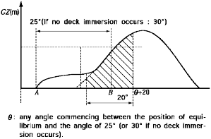
Fig 3.2.3 Range of positive stability
![]()