Iranian Classification Society Rules

< Previous | Contents | Next >
Section 3 Sea Pressures
301. Slamming pressure on bottom
1. Bottom slamming pressure
(1) Slamming pressure on the bottom of craft with speed ĐÕΡ̓ÜÃ ≥ 3 is to be as following for- mula :
Č Ì Įᾟ
ˇ LǾĮ
Ń ᾘLǾKÜJL Ň ƒÉ
NkNÕm Ī Ń
ᾯᾨ Ņ Ǿ
ᾨN ÜᾪA
ᾫ JL Ň ƒᾏᾛ ᾏᾛ
ᾟᾨ :
ᾪ :
A :
longitudinal distribution factor, taken from Fig 3.2.3.
Nos. of hull, (Mono hull craft = 1, Twin hull craft = 2)
design load area (mĪ) for element considered, however, A need not for any structure be taken less than 0.002(∆Õᾘ).
(A) plating : A is not to be taken greater than 2.5 Ċ Ī
(B) stiffener and girder : A Ņ Ċ ᾨ
Ċ : stiffener spacing (m )
ᾨ : stiffener or girder span (m )
ᾘL :
ă :
draft at à /2 (m ) at normal operation condition at service speed.
deadrise angle at transverse section considered. (maximum 30° minimum 10°)
ƒᾏᾛ Ø ᾍᾏᾛ : as given in 202. Par 3.
(2) The bottom slamming pressure need not be applied to craft with no significant hydrodynamic or air cushion lift in normal operating conditions.
(3) The bottom slamming pressure is to be applied on elements within the area extending from the
keel line to chine, upper turn of bilge or pronounced sprayrail.
Pt 3 Hull Structures
Ch 2 Design Loads Pt 3, Ch 2
![]()
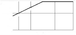
Fig 3.2.3 Longitudinal Slamming Pressure Distribution Factor (
(4) For transverse sections with no pronounced deadrise angle, to Fig.3.2.4.
and may be estimated according
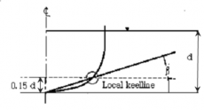
Fig 3.2.4 Deadrise angle for round bottom section
2. Pitching slamming pressure on bottom
(1) The pitching slamming pressure on bottom is to be taken following formula.
tan
factor taken from belows.
Platings : = 1.0
Stiffeners and girders :
: Longitudinal extend of load
area.
plates, longitudinal stiffener and girder : =
Transverse stiffeners and girders :
: Span of a stiffener and girder, ,m ax. = 1.0
lowest service speed draught (m ) at F.P. measured vertically from line or extended keel line.
as given in 301, Par 1.
: as given in 203, Par 1.
waterline to keel
(2) Above pressure is to extend within a length from FP and within Par 1. (3)
Pt 3 Hull Structures
Ch 2 Design Loads Pt 3, Ch 2
![]()
However, need not be taken as greater than is to be gradually reduced to at 0.175 aft of the above length.
(3) Pressure on the bottom structure given in Par 1 and Par 2 is not to be less than sea pressure as given in 304.
(4) Pitching slamming pressure is to be exposed on elements within
keel line to chine, upper turn of bilge or pronounced sprayrail.
the area, extending from the
302. Forebody side and bow impact pressure
1. Forebody side and bow impact pressure is to be taken as in
need not be taken greater than 3.0.
the following formula. However,
cos sin
load area for element considered (m ), however A is not to be taken greater than 2.5
m . In general, A need not be taken smaller than .
- plates : A is not to be taken greater than 2.5 m
- stiffeners and girders : A need not be taken smaller than m
correction factor for length of craft :
may reduced according to Table 3.2.3.
vertical distance in m from waterline at draught to the load point.
: vertical extent of load area, measured along shell perpendicular to the waterline.
: distance (m ) from to position considered.
correction factor for length of craft, however,
:
not be taken greater than 100 m
flare angle taken as the angle between the side plating and a horizontal line, measured at the point considered, refer to Fig 3.2.5.
angle between the waterline and a longitudinal line at the point considered, refer to Fig 3.2.6.
: acceleration factor :
as in the following formula, however, not be taken as greater than 0.2
: as given in 301, Par 1.
:
as given in 203, Par 1.
Pt 3 Hull Structures
Ch 2 Design Loads Pt 3, Ch 2
![]()

Fig 3.2.5 Angle
Fig 3.2.6 Angle
2. Forebody side and bow impact pressure given in 304. shall not be less than the sea pressure.
3. The impact pressure given in Par 1 is to extend a length as follows :
(1) The bow and 0.4 from FP
(2) In vertical direction, the impact pressure is to extend from the bottom chine or upper turn of bilge to main deck or vertical part of craft side. The upper turn of bilge is to be taken at a position where the deadrise angle reaches 70° but not higher than the waterline.
(3) If no pronounced bottom chine or upper turn of bilge is given (v-shape), the impact pressure is
to extend from the keel to main deck or from the vertical part of craft side.
303. Slamming pressure on flat cross structures
1. The slamming pressure on flat cross structures (catamaran tunnel top) is to be as following formula
:
kN
as given in 301. 1.
: minimum vertical distance (m ) from WL to load point in operating condition.
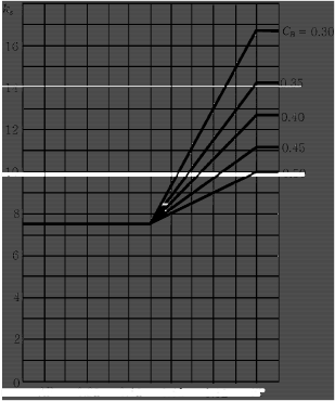
longitudinal pressure distribution factor, refer to Fig 3.2.7.
:
necessary vertical clearance (m ) from WL to load point to avoid slamming , as
formula.
following
: hull type clearance factor, refer to Table 3.2.4.
2. Slamming pressure given in Par 1 is not to be less than sea pressure, as given in 304.
Table 3.2.4 Hull Type Clearance Factor (
Hull type | Clearance factor |
Catamaran | 0.3 |
Wave piercer | |
SES, ACV | |
Hydrofoil, foil catamaran | |
SWATH | 0.5 |
Pt 3 Hull Structures
Ch 2 Design Loads Pt 3, Ch 2
![]()
304. Sea pressures
1. Pressure acting on the craft's bottom, side (including superstructure side) and weather decks be taken as below formulae :
(1) For load point below load line :
kN m
is to
kN
: vertical distance(m ) from the load line to the load point.
: longitudinal sea pressure distribution factor, refer to Fig 3.2.8.
= 7.5, aft of amidship.
= 5/ , forward of FP, between specified areas shall be varied linearly.
= 1.0, for craft's sides and open freeboard deck.
= 0.8, for weather decks above freeboard deck.
(3) In no case is the value of sea pressure to be less than the value given in Table 3.2.5.
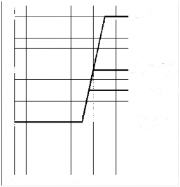
Fig 3.2.7 Flat Cross Structure Slamming Fig 3.2.8 Sea Load Distribution Factor (
Distribution Factor (
Pt 3 Hull Structures
Ch 2 Design Loads Pt 3, Ch 2
![]()
Table 3.2.5 Minimum Sea Pressure
(kN m
Notation | Sides | Weather decks | Roofs higher than 0.1 above |
SA0, SA1, SA2, SA3 | 6.5 | 5 | 3 |
SA4 | 5 | 4 | 3 |
SA5 | 4 | 3 | 3 |
2. The pressure on superstructure end bulkheads and deckhouses is not to be less than following formulae. However, it should not be less than min .
(1) For the lowest tier of unprotected front : min sin
(2) Elsewhere :
min sin
: the angle between the bulkhead and deck.
= 2.0, for lowest tier of unprotected front.
= 1.5, for deckhouse fronts.
= 1.0, for deckhouse sides.
= 0.8, elsewhere.
3. The pressure on watertight bulkheads (compartment flooded) is to be taken less than as formula :
following
: vertical distance (m ) from the load point to the top of bulkhead or to the flooded
water-
305. Liquids
1. The pressure in deep tanks is to be taken as the greater of the following formulae.
kN m
k N m , for ≤
kN m , for
as given in 202, Par 2.
: vertical distance (m ) from the load point to the top of tank
vertical distance (m ) from the load point to the top of air pipe or filling station
:
density of liquid (t m
), however not to be taken as less than 1.025
Pt 3 Hull Structures
Ch 2 Design Loads Pt 3, Ch 2
![]()
2. The pressure on wash bulkheads is to be as following formula :
: the greater distance (m ) to the next bulkhead forward or
306. Dry cargo, stores and equipment
1. The pressure on inner bottom, decks or hatch covers is to be taken as following formula :
kN
as given in 202, Par. 2.
: stowage height (m )
density of cargo (t m
: )
Table 3.2.6 Standard Load Parameters
Decks | Parameters (kN m ) |
Weather deck and weather deck hatch covers for cargo |
|
Sheltered deck, Sheltered hatch covers and inner bottom for cargo | t m : Vertical distance form the load point to the deck above. For load points below hatchways, is to be measured to the top of coaming |
Platform deck in machinery space (s) | t m |
Accommodation decks | t m |
307. Heavy units
The vertical force acting on supporting structures from structural components is to be as following formula :
rigid units of cargo, equipment or other
kN
: as given in 202, Par 2