Iranian Classification Society Rules

< Previous | Contents | Next >
Section 4 Hull Girder Loads
401. Longitudinal bending, shearing and axial loads
1. General
(1) For craft of ordinary hull form with less than 12, with length less than 50 , the mini-
mum strength requirements.
(2) For other types
standard is normally satisfied for scantlings obtained from local strength
of craft, with greater than 12, and for craft with length greater than 50 m
Pt 3 Hull Structures
Ch 2 Design Loads Pt 3, Ch 2
![]()
the longitudinal strength is to be calculated as described below.
2. Bending moment from slamming pressure
(1) For craft ≥3.0, a
slamming pressure is acting on an area equal to the reference area,
: as given in 202, Par 2
= 0.7 for crest landing
0.6 for hollow landing
(2) Crest landing moment
(A) The load combination illustrated in Fig 3.2.9 is to be required with tribution along the hull beam. The longitudinal midship bending moment However, ( ) is not to be taken as less than 0.04 .
actual weight dis- is to be as below.
∆
: as given in 202, Par 2.
: one half of the distance (m ) from LCG of the fore half to the LCG of aft half body of the craft. If not known, = 0.25 (0.2 for hollow
landing).
: breadth of the slamming reference area, refer to Fig
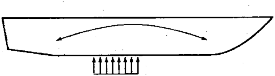
Fig 3.2.9 Crest Landing
(B) The reduction of towards ends will be determined by weight distribution and the extent of .
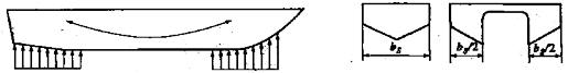
(3) Hollow landing moment
Hollow landing is similar to crest landing except that the reference area is situated towards AP and FP, refer to Fig 3.2.10. However, ( ) is not to be taken as less than 0.04
. The longitudinal midship bending moment is to be as following formula :
∆
kN m
: as given in 202, Par 2.
Pt 3 Hull Structures
Ch 2 Design Loads Pt 3, Ch 2
![]()
mean distance (m ) from the center of
: as given in preceding (2)
Fig 3.2.10 Hollow Landing
/2 end areas to craft LCG
Fig 3.2.11 Breadth of Midship Slamming Reference Area
3. Planning moment of hydrofoils
Hydrofoils longitudinal strength is to be calculated for the most severe conditions. As a rule, this will consider the craft as sustained above the water surface by the foils, and stationary in the navi- gation condition, taking into account vertical acceleration as well as vertical components of the hy- drodynamic action of the water on the foils.
4. Hogging and sagging bending moments
Investigation of sagging and hogging bending moment (still water + wave), taking into account any immersed/emerged structures, may be required for all craft.
(1) Monohull craft
kN m
kN m
: as given in 203, Par 1.
: still water bending moment in the most unfavourable loading condition (kN m )
if hogging is not known =
if sagging is not known = 0 NOTES :
1) Documentation of the most unfavourable still water condition is normally to be submitted for information.
2) If still water bending moment is hogging moment, 50 % of this moment may be deducted where the design sagging moment ( ) is calculated.
(2) Twin hull craft
kN m
kN m
: still water bending moment in the most unfavourable loading condition (kN m )
if hogging is not known = 0.5 ∆ (kN m ) if sagging is not known = 0
NOTES :
1) Documentation of the most unfavourable still water condition is normally to be submitted for information.
2) If still water bending moment is hogging moment, 50 % of this moment may be deducted where the design sagging moment ( ) is calculated.
Pt 3 Hull Structures
Ch 2 Design Loads Pt 3, Ch 2
![]()
: breadth of cross structure (m ).
and : factors for the effect of cross structure immersion in hogging and sagging wave as below. however, not to be taken as less than 0.0
: height (m ) from base line to wet deck (top of the tunnel)
5. Shear forces from longitudinal bending
Shear forces of vertical hull girder is to be as following formula :
kN
: bending moment (kN m ) as given in preceding Par 2. (2) and (3).
6. Axial loads
Axial loads
∆ ), thrust and sea end pressure are to be in exposed areas.
: maximum surge acceleration is not to be less than following
≥
with linear interpolation for intermediate
402. Twin hull loads
1. General
(1) The transverse strength of the twinhull connecting structure is to be analysed for moments and forces as specified below.
(2) Design forces and moments are to be used unless other values are verified by model full scale measurements, or if similar structures provided are satisfactory in service.
(3) Superstructure is normally not to be included in the structure for transverse strength.
2. Transverse bending moment and shear force
(1) For the twinhull transverse bending moment of craft with ≥ 3.0 and m
tests or
refer to
kN m
: transverse distance (m ) between the centerlines of the two hulls.
: factor given in Table 3.2.7.
Pt 3 Hull Structures
Ch 2 Design Loads Pt 3, Ch 2
![]()
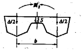
Fig 3.2.12 Transverse Vertical Bending Moment and Shear Force
(2) For craft with ≥ m , the twinhull transverse bending moment is to be the greater of
ing formula.
can here be taken as the waterline breadth at and
not to
be taken greater than 3.
kN m
kN m
: transverse bending moment in still water (kN m ) 【See Guidance】
: horizontal split force on immersed hull, as following
kN
C 1
![]()
= 1.6 - 6
L
C2
= 70
L
d
: height ( ) from base line to wet deck (top of the tunnel).
(3) The vertical shear force in centerline between twinhull is to be as following formula :
kN
: factor given in Table 3.2.7
3. Pitch connecting moment
The twinhull pitch connecting moment is, refer to Fig 3.2.13 to be as following formula :
kN m
Table 3.2.7 Factors
and
![]()
Service restriction |
|
|
SA4 | 8.0 | 6.0 |
SA3 | 7.5 | 5.5 |
SA2 | 6.5 | 5.0 |
SA1 | 5.5 | 4.0 |
SA0 | 4.0 | 3.0 |

Fig 3.2.13 Pitch Connecting Moment on
Twinhull Connection
4. Twinhull torsional moment
The twinhull torsional moment is to be as following formula
kN m
![]()
: as given in Par 2
![]()