Iranian Classification Society Rules

< Previous | Contents | Next >
Section 4 Hull Girder Strength
401. General
1. Requirements for longitudinal and transverse hull girder strength are given in this section. In addi- tion, buckling control may be required.
2. For the craft types and sizes mentioned in Ch 2, Sec 4, longitudinal strength has to be checked.
3. For large, complicated crafts, such as multihull types, a complete, 3-dimensional global analysis of the transverse strength, in combination with longitudinal stress, is to be carried out.
4. Buckling strength in the bottom and deck is to be inspected.
402. Deck corners
Moulded deck line, rounded sheer strake, sheer strake and stringer plate are defined in Fig 3.3.3.
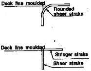
Fig 3.3.3 Deck Corners
403. Vertical bending strength
As defined, hull section modulus ( ) in midship, is to be greater than as following formula
×
c
: longitudinal midship bending moment (kN m )
![]()
= as defined in Ch 2, 401, Par 2, monohull, catamaran and SES in crest and hollow landing.
= as defined in Ch 2, 401, Par 3, hydrofoil on foils.
= as defined in Ch 2, 401, Par 4, hydrofoil in slowed down condition, ACV, high-speed displacement craft and semi-planning craft in displacement mode.
: allowable bending stress as follows.
N mm , in general
N mm , hydrofoil on foils
N mm , planning craft in slowed-down
: as condition defined in 501. Par 3.
404. Effective section modulus
The calculation of section modulus is to be in accordance with
the Classification of Steel Ships.
Pt 3, Ch 3, 203. of Rules for
405. Shear strength
1. If doors are arranged in the craft side, the required sectional area be specially considered.
of the remaining side plating will
2. If rows of windows are arranged below the strength deck, sufficient horizontal shear area must be arranged to carry down the midship tension and compression.
3. In these and formula.
other locations with doubtful shear areas, may be taken according to the following
N m m
406. Transverse strength of twin hull craft
1. Transverse strength
(1) The twinhull connecting structure is to have adequate transverse strength related to the design loads and moments in Ch 2.
(2) When calculating the moment of inertia and section modulus of the longitudinal section of the
connecting structure, the effective sectional area of transverse strength members is in general the net area with effective flange after deduction of the openings. The effective shear area of trans- verse strength members is in general the net area after deduction of the openings.
2. Allowable stresses
When the calculating the strength of twinhulls, applied in loads, and defined in Ch 2, 402, the al- lowable stress are to be followed.
(1) Normal stress : N mm
(2) Mean shear stress :
N mm
(3) Equivalent stress :
Equivalent stress is defined as following formula :
total normal stress in x-direction.
: total normal stress in y-direction.
total shear stress in xy-plane.
Total stress means the arithmetic sum of stresses from hull girder, local forces and
![]()
moments.
: as defined in 501. Par 3.
407. Buckling strength
The strength deck or side plating is to be endured the buckling strength subject to hull girder bending stress.