Iranian Classification Society Rules

< Previous | Contents | Next >
Section 5 Sandwich Panels
501. Consideration of buckling
Buckling strength of sandwich panels related to longitudinal hull girder strength or local axial loads are to be dealt with individually.
502. Minimum requirements to structural sandwich panels
1. The reinforcement of skin laminates is to contain at least 40 % continuous fibres.
2. The mechanical properties of the core material of structural sandwich panels are to comply with the following minimum requirements (refer to Table 3.5.1).
![]()
Table 3.5.1 Mechanical Properties of Sandwich Panels
Structural members | Core properties (N mm ) | |
Shear strength | Compression strength | |
Hull bottom, side and transom below deepest WL or chine whichever is higher | 0.8 | 0.9 |
Hull side and transom above deepest WL or chine whichever is higher | 0.8 | 0.9 |
Weather deck not intended for cargo | 0.5 | 0.6 |
Cargo deck | 0.8 | 0.9 |
Accommodation deck | 0.5 | 0.6 |
Structural/watertight bulkheads/double bottom | 0.5 | 0.6 |
Superstructures/Deckhouses | 0.5 | 0.6 |
Tank bulkheads | 0.5 | 0.6 |
3. The mass of reinforcement (g m ) in skin laminates in structural sandwich panels should normally not be less than the following. However, Details including laminating process such as work sheets to be submitted.
≥
for m
: mass of reinforcement per unit area,
: given in Table 3.5.2 (For mixed material reinforcements can be found by linear inter- polation in the table according to the relative percentage of each material with respect to weight per unit area.)
given in Table 3.5.2.
: length between perpendiculars.
4. Deviation from the minimum requirements may be accepted by the Society on consideration of craft type and service restriction or based on documentation of equivalent resistance to loads de- scribed in Table 3.5.1.
![]()
Table 3.5.2
and
Structural Member |
|
|
|
| |
Glass | Carbon/Aramid | ||||
Hull bottom, side and transom below deepest WL or chine whichever is higher | 2400 | 1600 | 0.025 | ||
Hull side and transom above deepest WL or chine whichever is higher | 1600 | 1100 | 0.025 | ||
Hull bottom and side, inside of hull | 1600 | 1100 | 0.013 | ||
Stem and keel, (width to be defined) | 6000 | 4000 | 0.025 | ||
Weather deck (not for cargo) | 1600 | 1100 | 0.0 | ||
Wet deck | 1600 | 1100 | 0.0 | ||
Cargo deck | 3000 | 2000 | 0.013 | ||
Accommodation deck, if adequately protected | 1200 | 800 | 0.0 | ||
Accommodation deck, other | 1600 | 1100 | 0.0 | ||
Decks, underside skin | 750 | 500 | 0.0 | ||
Deep tank bulkheads/double bottom | 1600 | 1100 | 0.0 | ||
Structural bulkheads | 1200 | 800 | 0.0 | ||
Watertight bulkheads | 1600 | 1100 | 0.0 | ||
Superstructure and deckhouse, outside | 1200 | 800 | 0.013 | ||
Inside void spaces without normal access | 750 | 500 | 0.0 | ||
503. Bending
1. Normal stresses in skin laminates and core shear stresses
(1) Maximum normal stresses in the skin laminates of a sandwich panel subject to uniform lateral pressure is given by the following formula :
N m m
: For stresses parallel to the longest edge, refer to Fig 3.5.4.
: For stresses parallel to the shortest edge, refer to Fig 3.5.4.
: section modulus of the sandwich panel per unit breadth (mm mm ). For a sandwich- panel with skins of equal thickness =
: factor, as defined in follows.
= 1.0, for panels with simply supported edges.
= or
according to Fig 3.5.5, for panels with fixed edges or partially fixed
edges.
for stresses parallel to the longest edge.
for stresses parallel to
shortest edge.
(2) The maximum core shear stresses at the midpoints of the panel edges of a sandwich panel sub- ject to lateral pressure is given by the following formula :
N mm
![]()
= , for core shear stress at midpoint of longest panel edge, see Fig 3.5.6.
= for core shear stress at midpoint of shortest panel edge, see Fig 3.5.6.
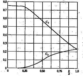
Fig 3.5.4 Factors
and
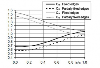
Fig 3.5.5 factor
![]()
Fig 3.5.6 Factors
and
2. Local skin buckling
The critical local buckling ing formula :
stress for skin laminates exposed to compression is given by the follow-
N mm
3. Deflection
The deflection at the midpoint of a flat panel is given by the following formula :
and : refer to Table 3.5.7.
: factor, as defined in follows.
= 1.0, panels with simply supported edges.
= refer to Fig 3.5.8, panels with fixed edges or partially fixed.
: modulus of elasticity, refer to Table 3.5.3.
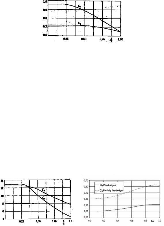
Fig 3.5.7 Factors
and
Fig 3.5.8 Factor
![]()
Table 3.5.3 Modulus of Elasticity
| |
For panels with skin laminates with equal thickness and modulus of elasticity |
|
For panels with skin laminates with different thickness and modulus of elasticity |
|
NOTE : 1 and 2 : inner and outer skin respectively. | |
4. Allowable stresses and deflections
The maximum normal stresses in skin laminates, core greater than given values in following Table 3.5.4.
shear stresses and deflection are not to be
![]()
Table 3.5.4 Allowable Stresses and Deflection
Structural member |
|
|
|
Bottom panels exposed to slamming | 0.3
| 0.35
| 0.01 |
Remaining bottom and inner bottom | 0.3 | 0.4 | 0.01 |
Side structures | 1.3 | 1.4 | 0.01 |
Deck structures | 1.3 | 1.4 | 0.01 |
Bulkhead structures | 0.3 | 0.4. | 0.01 |
Superstructures | 1.3 | 1.4 | 0.01 |
Deckhouses | 0.3 | 0.4 | 0.01 |
All structures exposed to long time static loads | 0.20 | 0.15 | 0.005 |
NOTE: (1) is to be in accordance with the following : For skin laminates exposed to tensile stress : ultimate tensile stress. For skin laminates exposed to compressive stress :the smaller of the ultimate compressive stress and critical local buckling stress. (2) The allowable stress level for bottom panels exposed to slamming loads refer to core materials with a shear elongation of at least 20 % an increase of the allowable stress level may be accepted upon special consideration. | |||
![]()