Iranian Classification Society Rules

< Previous | Contents | Next >
Section 6 Single Skin Construction
601. Consideration of buckling
Buckling strength of single skin panels subjected to longitudinal hull girder strength or local com- pressional loads will be dealt with individually.
602. Minimum requirements to structural single skin plates
1. The reinforcement of single skin laminates is to contain at least 40 % continuous fibres.
2. The mass of reinforcement (g/m2) in single skin panel should normally not be less than following: However, details including laminating process such as work sheets to be submitted.
≥
for m
:
:
mass of reinforcement per unit area, g m
given in Table 3.5.5. (For mixed material reinforcements can be found by linear
terpolation in the table according to weight per unit area.)
given in Table 3.5.5.
: length between perpendiculars.
to the relative percentage of each material with respect
Table 3.5.5 and
Item |
(g m |
|
Hull bottom, side and transom below deepest WL or chine whichever is higher | 4200 | 0.025 |
Hull side and transom above deepest WL or chine whichever is higher | 4200 | 0.025 |
Stem and keel to 0.01 L from centreline | 7500 | 0.025 |
Chine and transom corners to 0,01 L from chine edge | 5800 | 0.025 |
Bottom aft in way of rudder, shaft braces, and shaft penetrations | 6600 | 0.025 |
Weather deck not intended for cargo | 4200 | 0.0 |
Cargo deck | 5400 | 0.013 |
Accommodation deck | 2900 | 0.0 |
Structural/watertight bulkheads/ double bottom | 4200 | 0.0 |
Tank bulkheads | 4500 | 0.0 |
Other bulkheads | 2500 | 0.0 |
Superstructures and deckhouses | 4200 | 0.013 |
603. Laterally loaded single skin laminates
1. Assumptions
(1) The formulas given below are valid under the following assumptions.
(A) The principal directions of reinforcement are parallel to the edges of the panel.
![]()
(B) The difference in the modulus of elasticity in the two principal direction of reinforcement is not more than 20 %.
![]()
(C) The load is uniformly distributed.
(2) For laminates not complying with the above (1) are to be in accordance with the discretion of the Society.
2. Laminates exposed to combined bending and membrane stresses.
(1) For a given design pressure the thickness requirements are related to a laminate deflection factor
(=/t) and an allowable combined stresses (bending stress + membrane stress).
(2) The required thickness to meet a specific value of d in association with a given design pressure
is given by the following formula :
mm
and : refer to Table 3.5.9.
(3) The combined stresses (bending stress + membrane stress) corresponding to the thickness found in (2) is given the following formula :
N mm
and
: refer to Fig 3.5.9.
: refer to Fig
Fig 3.5.9 Factors
and
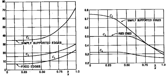
Fig 3.5.10 Factors and
3. Allowable stresses and deflections
The maximum combined stresses (bending stress + membrane stress) and deflections are not to be greater than given values in the Table 3.5.6.
![]()
Table 3.5.6 Allowable Stresses and Deflection
Structural member | σ c | δ |
Bottom panels exposed to slamming | 0.3 σ nu | 1.0 |
Remaining bottom and inner bottom | 0.3 σ nu | 0.9 |
Side structures | 0.3 σ nu | 0.9 |
Deck structures | 0.3 σ nu | 0.9 |
Bulkhead structures | 0.3 σ nu | 0.9 |
Superstructures | 0.3 σ nu | 0.9 |
Deckhouses | 0.3 σ nu | 0.9 |
All structures exposed to long time static loads | 0.2 σ nu | 0.5 |
604. Stiffeners
1. Section modulus
(1) The section modulus of longitudinals, beams, frames and other stiffeners subject to lateral pres- sure is not to be less than that obtained from the following formula :
c
bending moment factor, defined in Sec 7, Table 3.5.10 for load and boundary con- ditions, and Table 3.5.8 for structural members.
spacing of stiffeners (m ).
: span of the stiffeners (m ).
: allowable stress, defined in Table 3.5.7.
(2) When calculating the section modulus of top hat stiffeners the effect of possible variations in
the modulus of elasticity through the section should be taken be determined in accordance with 704. Par 2.
into account. Effective flange is to
![]()
![]()
structures |
|
Continuous longitudinal members | 85 |
Non-continuous longitudinal members | 100 |
Transverse members | 100 |
Vertical members, and fixed | 100 |
Vertical members, simply supported | 135 |
Bottom longitudinal members | 85 |
Bottom Transverse members | 100 |
Side longitudinal members | 85 |
Side vertical members | 100 |
Deck longitudinal members | 85 |
Deck Transverse members | 100 |
W.T. bulkhead stiffeners, fixed ends | 65 |
W.T. bulkhead stiffeners, fixed one end (lower) | 85 |
W.T. bulkhead stiffeners, simply supported ends | 125 |
Tank and cargo bulkhead, fixed ends | 100 |
Tank and cargo bulkhead, simply supported ends | 135 |
Deckhouse stiffeners | 100 |
Casing stiffeners | 100 |
Table 3.5.7 Allowable Stresses Table 3.5.8 Bending Moment Factor ( )
Structural member |
|
Bottom plates exposed to slamming | 0.25 |
Remaining bottom and inner bottom | 0.25 |
Side structures | 0.25 |
Deck structures | 0.25 |
Bulkhead structures | 0.25 |
Superstructures | 0.25 |
Deckhouses | 0.25 |
All structures exposed to long time static loads | 1.15 |
![]()