Iranian Classification Society Rules

< Previous | Contents | Next >
Section 7 Transverses and Girders
701. General
In this section, the general requirements for simple girders and procedures for the calculations of
complex girder systems are given. The buckling strength of girders will be considered.
dealt with individually
702. Symbols
In this chapter the symbols in formulas are as follows.
girder span (m ), the web height of in-plane girders may be deducted.
: breadth of load area (m ), refer to Table 3.5.9.
design pressure, defined in Ch 2.
:
design axial force (kN).
: nominal allowable bending stress due to lateral pressure (N mm
). nominal allowable shear stress (N mm ).
: nominal allowable bond shear stress (N mm
). web thickness (mm ).
:
web height (mm ).
: flange breadth (mm ).
Table 3.5.9 Breadth of Load Area
| |
For ordinary girders | m |
For hatch side coamings | m |
For hatch end beams | m |
NOTE: and : the span (m ) of the supported panels. : breadth of craft (m ) measured at the middle of hatchway. : breadth of hatch (m ) measured at the middle of hatchway. : distance (m ) between hatch end beam and nearest deep transverse girder or trans- | |
703. Continuity of strength members
1. Structural continuity is to be maintained at the junction of primary supporting members of unequal stiffness by fitting well rounded brackets. Brackets ending at unsupported sandwich panels are to be tapered smoothly to zero and the panels skin laminate to be locally reinforced at the end of the bracket. Girders are to be fitted with bracket or tapered to zero at their ends, (refer to, Fig 3.5.11).
2. Where practicable, deck pillars are to be located in line with pillars above or below. Massive or high density core inserts are to be fitted at the foot of pillars.
3. Below decks and platforms, strong transverses are to be fitted between verticals and pillars, so that rigid continuous frame structures are formed.
704. Bending and shear
1. General
![]()
(1) The requirements for section modulus and web area given in this chapter are applicable to sim-
![]()
ple girders supporting stiffeners or other girders exposed to linearly distributed lateral pressure. It is assumed that the girder satisfies the basic assumptions of simple beam theory and that the supported members are approximately evenly spaced and simply supported at both ends. Other loads will have to be specially considered.
(2) When boundary conditions for individual girders are not predictable due to dependance of ad- jacent structures, direct calculations according to the discretion of the Society will be required.
2. Effective breadth
The effective panel flange area is defined as Fig 3.5.12. For top-hat
girders supporting sandwich
panels only the skin laminate at which breadth.
the girder is fitted
should
be considered as effective
Fig 3.5.11 Ends of Girders

Fig 3.5.12 Effective Breadth (be)
3. Effective web
(1) Holes in girders will generally be accepted provided the shear stress level is acceptable and the buckling strength is sufficient. Holes are to be kept well clear of end of brackets and locations where shear stresses are high.
(2) For ordinary girder cross-sections the effective web area is to be taken as following formula :
cm
: net girder height (mm ), after deduction of cutouts in the cross-section considered. If
an opening is located at a distance less than from the cross-section considered,
is to taken as the smaller of the net height and the net distance through the opening, refer to Fig 3.5.13.
(3) Where the girder flange is not perpendicular to the considered cross section in the girder, the
sin cm
: as defined in previous
![]()
: flange area (cm

: angle of slope of continuous flange.
Fig 3.5.13 Effective Web Area in Way of Openings
Fig 3.5.14 Effective Web Area in Way of Brackets
4. Effective bond area
For girders attached to other structural members at their supports by secondary bonding the effec- tive bond area is determined by the following formula, (refer to Fig 3.5.15).
cm
Fig 3.5.15 Effective Bond Area
5. Scantlings of girders
(1) The section modulus for girders subjected to lateral pressure is not to be less than that obtained from the following formula :
cm
: bending
moment factor, defined in (5).
When calculating the section modulus of top hat profiles the effect of possible varia- tions in the modulus of elasticity throughout the section should be taken into account.
(2) The web area of girders subject to lateral pressure is not to be less than that obtained from the following formula :
![]()
cm
: shear force factor, defined in (4).
(3) The bond area, between girders and their supporting structure, at the girders ends is not to be less than that obtained from the following formula :
c
: shear force factor, defined in (4).
the ultimate bond shear stress for the secondary bonding.
(4) The m and
3.5.10, not
values are given for some defined load and boundary conditions in Table
defined in previous Table, -values are directly from general elastic bending
theory. For girders where brackets are fitted or the flange area has been partly increased due to large bending moment, a larger m-value may be accepted outside the strengthened region.
(5) The and values referred in (1) and (2) are normally to be as various structural members.
Table
3.5.11 for the
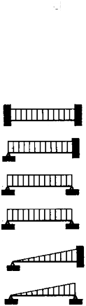
Table 3.5.10 Values of
and
Load and boundary conditions | Boundary moment and shear force factors | ||||
Positions | 1 | 2 | 3 | ||
1 Support | 2 Field | 3 Support |
|
|
|
| - |
| |||
85 | 42 | 85 | |||
0.50 | 0.50 | ||||
0.38 | 70 | 125 0.63 | |||
0.50 | 125 | 0.05 | |||
65 | 43 | 100 | |||
0.30 | 0.70 | ||||
0.20 | 60 | 135 0.80 | |||
0.33 | 130 | 0.67 | |||
![]()
Table 3.5.11 Factors
and
|
| ||
Bottom | Transverses Floors Longitudinal girders | 100 100 100 | 0.63 |
Side | Longitudinal girders | 100 | 0.54 |
Transverses, upper end Transverses, lower end | 100 100 | 0.54 0.72 | |
Deck girders | 100 | 0.63 | |
Bulkhead | Horizontal girders | 100 | 0.54 |
Vertical girders, upper end | 100 | 0.54 | |
Vertical girders, lower end | 100 | 0.72 | |