Iranian Classification Society Rules

< Previous | Contents | Next >
Section 2 Construction
201. Thickness
The thickness of bulkhead plating is not to be less than obtained from the following formula:
ᾼ Ņ ĮǾĪ ĊΡ̓Üᾜ Ñ ÌǾJ (m)
where:
Ċ = Spacing of stiffeners (m)
ᾜ = Vertical distance measured from the lower edge of the plates to the bulkhead deck at the centre line of barge (m), but in no case is it to be less than 3.4 m.
202. Increase of thickness
1. The thickness of the lowest strake of bulkhead plating is to be at least l mm thicker than obtained from the formula in 201.
2. The lowest strake of bulkhead plating is to extend at least about 600 mm above the top of inner bottom plating in way of double bottom or about 900 mm above the top of keel in way of single
![]()
bottom. Where the double
bottom is provided only on one side of the bulkhead, the extension of
the lowest strake is to be effected up to either height according to the preceding sentence, which- ever is the greater.
3. The bulkhead plating in bilge well is to be at least 2.5 mm thicker than given in 201.
4. The thickness of deck plating in way of bulkhead recesses is to be at least 1 mm greater than that
given by 201., regarding the deck plating as respectively. In no case is the thickness to be location.
bulkhead plating and the beams as stiffeners less than the required for deck plating in the
203. Stiffeners
The section modulus of bulkhead stiffeners is not mula:
to be less than obtained from the following for-
Ě Ņ ǼĊᾜᾨĪ (cm3)
where:
Ǽ = Coefficients given in Table 14.1 according
Ċ = Spacing of stiffeners (m)
to the type of end connection
h = Vertical distance measured from the mid-point of l
for vertical stiffeners, and from the mid-
point of the distance between the adjacent stiffeners for horizontal stiffeners, to the top of bulkhead deck at the centre line of barge (m). Where the vertical distance is less than 6.0 m, h is to be taken as 0.8 times the vertical distance plus 1.2 m
l = Span measured between the adjacent supports of stiffeners including the length of connection
(m). Where girders are provided,
l is the distance from the heel of end connection to the
first girder or the distance between the girders.
204. Collision bulkheads
For collision bulkheads, the plate thickness and section modulus of stiffeners are not to be less
than those specified in 201. and 203. taking
h as 1.25 times the specified height.
205. Girders supporting bulkhead stiffeners
1. The section modules of girders not to be less than obtained from the following formula:
Ě Ņ ĨǾKJ ĊᾜᾨĪ
(cm3)
where:
Ċ = Breadth of the area supported by the girder (m)
h = Vertical distance measured from the mid-point of l
for vertical girders, and from the
mid-point of S for horizontal girders, to the top of upper deck at the centre line of barge
(m). Where the vertical distance is less than 6.0 m, tical distances plus 1.2 m.
l = Span between the supports of girders (m)
h is to be taken as 0.8 times the ver-
2. The moment of inertia of girders is not to be less than that obtained from the following formula.
In no case is the depth of girders to be less than 2.5 times the depth of slots for stiffeners.
Ā Ņ ÌL ᾜᾨĨ (cm4)
![]()
where:
h, l = As specified in Par 1.
3. The thickness of web plates is not to be less than obtained from the following formula:
ᾼ Ņ LǾLÌ ĊÌ Ñ ÌǾJ (mm)
where:
ĊÌ = Spacing of web stiffeners or depth of girders, whichever is the smaller (mm)

![]()
Table 14.1 Value of Ǽ
Verti c a l Stiff ener | Lower end | Upper end | Lug-connection, supported by girders or hard connection | Soft connection | End of stiffener unattached |
Lug-connection or supported by girders | 2.80 | 3.22 | 3.78 | ||
Bracketed | 2.24 | 2.52 | 2.80 | ||
Only the web of stiffener attached at end | 3.22 | 3.78 | 4.48 | ||
End of stiffener unattached | 3.78 | 4.48 | 5.60 | ||
Ho ri zo n- t a l Stiff ener | The other end | One end | Lug-connection, supported by girders or Hard connection | End of stiffener unattached | |
Lug-connection bracketed or supported by brackets | 2.80 | 3.78 | |||
End of stiffener unattached | 3.78 | 5.60 | |||
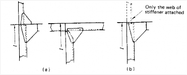
NOTES: 1. "Lug-connection" is such a connection as both web and face bar of stiffener are effectively attached to the bulkhead plating, decks or inner bottoms which are strengthened by effective supporting members on the opposite side of plating. 2. "Hard connection" of vertical stiffeners is a connection by bracket to the longitudinal members or to the adjacent members, in line with the stiffeners, of the same or larger section. (See Fig 14.1 (a)). 3. "Soft connection" of vertical stiffeners is a connection by bracket to the transverse members such as beams, or other connections equivalent to the connections mentioned above. (See Fig 14.1 (b)).
Fig 14.1 Types of end connection | |||||
![]()
4. Tripping arranged
brackets are to be provided at an interval of about 3 m, and these brackets are to be so as to support the face plates. ![]()
![]()