< Previous | Contents | Next >
Section 3 Periodical and Other Survey
301. Kinds of Surveys
Kinds of Survey shall apply to the requirements of Pt 1, Ch 3, Sec 1 of the Rules.
302. Performance of Survey
For Surveys of tourist submersibles registered on the Society, the following items shall be complied with.
1. Intermediate Survey
(1) Visual inspection
(2) Operation test of
(3) Insulation test of
of pressure hull
open/close indicating devices electrical equipments
(4) Operating test of controlled water depth devices.
(5) Performance test of Battery
(6) Function test of air conditioning.
(7) Verification of calibration for water depth meters, Hydrogen gas detector and those removing devices, pressure gauge of pressure vessel. navigation aids, etc.
(8) Where fitted things such as emergency drop weights, balancing chains, transmission cables or distress signal buoy, etc. For the emergency drop weights, the separation and drop test is to be carried out while the submersibles may be placed in a drydock or upon a slipway.
2. Special survey
In addition th the intermediate survey, the following requirements shall be complied with.
(1) Internal inspection for each tanks (including buoy tank)
(2) If necessary, Visual inspection for external pressurized windows, covers, pipes and valves, and drainage pumps and moving steel attachments separated which pass through pressure hull.
(3) If needed by the Society, the thickness of pressure hull's plate and frame tripping shall be measured.
(4) Overhaul inspection for propulsion machinery and auxiliary machine, etc. and the visual in-
spection for pressure vessels and those relevant piping system
(5) Function test for shipborne barometer low alarm devices and equivalent ones used for same purpose.
(6) For evacuation apparatus other than escape method to fill waters with one compartment of pres- sure hull, the function test of the evacuation is to be carried out.
(7) Running speed test under water
(8) Performance test at maximum diving depth.
(7) Running speed test under water at Maximum diving depth
(8) Performance test at 1.5 times of maximum diving depth : after reaching 1.5 times of max. div- ing depth, or equivalently pressurized, following items is to be confirmed.
(a) Pressure hull should not have any deformation and/or leakage.
(b) Viewport, access hatch and hatch cover should not have any deformation and/or leakage.
(c) Watertight parts which is penetrated by Pipes, cables and etc should not have any leakage.
(d) Drainage pump operation test is to be carried out
(9) Function test of Life Support Systems
(a) All life support piping systems, including gas storage containers, are to be pressurized to the design pressure, using the fluid normally used in service, and tested for leakage.
(b) Gas storage containers are to be hydrostatically pressure tested to 1.25 design pressure and
visually inspected internally (with a borescope) and externally, at least once during each Special Survey period and documents of such tests are to be maintained and reviewed.
(c)
(d)
Alternatively, gas storage cylinders are to be hydrostatically pressure tested and visually in- spected internally (with a borescope) and externally, at least once every 5 years by a quali-
fied third party in accordance with the requirements of the code/standard of manufacture
(such as the US Department of Transport (DOT) requirements).
Where gas storage containers are fastened to the vessel's structure, bolts are to be removed for examination including the condition of the pressure vessels in way of the bolts.
![]()
42 Guidance Relating to the Rules for the Classification of Underwater Vehicles 2015
Pt 3 Tourist Submersibles
Ch 1 Tourist Submersibles Pt 3, Ch 1
![]()
303. Submission of records
The owners, when the periodical survey and other survey is completed, shall be required to submit to the Society the survey records such as ship's conditions, measured results, wear down dimension, etc.
304. Hull Construction
1. Freeboard, etc. in buoyancy
(1) For tourist submersibles requiring towing, when buoying, the freeboard shall be kept appropriately.
(2) For tourist submersibles designed to allow person to exit during buoy, when buoying, the exit
height of pressure hull is to be sufficiently higher than water level
2. Provision against corrosions
Where the main parts of tourist submersibles are apt to get the corrosion, a proper protection against corrosion shall be taken or the thickness is to be increased as considering the materials used and environment condition, etc,.
3. Provision against external damages
(1) The pressure hull shall be kept from getting damages when berthing, etc.
(2) For the hull structures other than pressure hull, during diving voyage, if it is apt to get me- chanical damage or there is a part to give a significant effect to the tourist submersible's safety owing to these damages, it shall be protected or reinforced.
4. Provision of submersibles sailing on the water
For tourist submersibles sailing on the water after buoying, even though the window covers are closed, they shall be designed so that the water is visible or equivalent proper apparatus are to be provided. However, it may be not applied that the tourist submersibles are able to sail under the condition of opening of window covers.
5. Materials of Construction
(1) The approved materials used for pressure hull shall be complied with Pt 1, Ch 5, Table 2.5.2
of the Rules.
(2) The materials consisted of other significant part of hull shall be complied with Pt 1, Ch 1 of the Rules, and they shall be approved by the Society and have a sufficient strength based on the purpose used.
6. Fire protection materials
(1) The materials consisted of pressure hull, as far as practicable, shall be of non-combustible.
(2) As far as practicable, no ignition-source is to be at any position. Electrical heating devices and insulators are to include protection devices against over-heating.
(3) Their components and materials used shall be of those to minimize the static electricity. If the
flammable materials are provided in enclosed spaces, the fire-fighting system shall be designed to operate effectively outside the spaces.
7. Construction of pressure hull
(1) The pressure hull shall have sufficient strength to the external pressure having 2.0 times max, pressure at maximum diving depth.
(2) The external pressurized windows, covers, pipes and valves, etc. attached to pressure hull shall
be consructed so sufficiently considerable that the strength is equivalent to a compressed strength of non-opening of pressure hull
(3) For watertight parts of pressure hull which is penetrated by pipes, cables, shafts, etc., they shall
be sufficient to meet watertight at 1.5 times of max. diving depth.
8. Stress relieving of pressure hull
In considering construction of pressure hull, using materials, welding connection type and welding method, if needed by the Society, the stress relieving for pressure hull shall be taken.
![]()
Guidance Relating to the Rules for the Classification of Underwater Vehicles 2015 43
Pt 3 Tourist Submersibles
Ch 1 Tourist Submersibles Pt 3, Ch 1
![]()
9. Construction member other than pressure hull
For construction member other than pressure hull and consisting of hull construction, the tourist submersible shall be sufficient to meet strength under normal working condition.
305. Construction and system for diving and buoy
1. Construction and system for diving and buoy
(1) For diving and buoyancy, the buoy control system(buoy tank, trim control system) shall be provided. In this case, the size and construction of buoy tank, when buoying, shall be made to keep the required freeboard and the stability. And even if diving under declining condition, it shall be able to accumulate the airs.
(2) For the buoy tank, the venting valves shall be fitted so that the air is to be shut down or ex- hausted and buoyancy-air pipes shall be provided. In this case the air piping system is to be sufficiently arranged to prevent the buoyancy-air pipes from damaging outside.
(3) For pressure vessel having high pressure air for buoyancy, its capacity shall be sufficient based on the size of pressure hull, maximum diving depth, etc. And the vessel is to be firmly at- tached to the hull and be sufficient to prevent the vessels from damaging outside. Inside the
pressure hull the indicating devices for air condition of the vessel shall be provided at the posi-
tion to see easily.
(4) In maximum diving depth the apparatus to control hull's weight and trim shall be provided. this apparatus shall be sufficient to control the buoying speed.
(5) When discharging pump is used as the apparatus specified in above (4), the pump shall be de-
signed to pump out fully at the discharging pressure higher than that related to 1.2 times max- imum diving depth. At the outlet of discharging pump the check valve shall be fitted.
(6) Each tank installed inside pressure hull shall be made to get a proper volume based on the re-
quest of navigation and to fit the indicator pointing out air-exhausting and the quantities. However, inside these tanks penetrated pipes passing through pressure hull shall not be fitted.
2. Construction and system for life-saving, etc.
(1) For buoying in emergency, the emergency drop weight having a sufficient heft shall be provided. In this case emergency drop weight shall be provided with the releasing devices inside the pressure hull at maximum diving depth. The weight, after releasing, shall be arranged so that the tourist submersible is not inclined or overthrown. And if electric power is only used for operating of emergency buoy device, the emergency source is to be fitted so that the feeder is solely able to supply to this device.
(2) Where pressure vessel having high pressure air for emergency buoy is ready or equivalent other apparatus ready, the emergency drop weight may be omitted.
(3) In emergency person shall be able to escape from pressure hull. However, when it is permitted
not to disturb them in considering the using purpose, the diving water area, the maximum div- ing depth and the efficiency of related devices, etc., it may be dispensed with and then the matter shall be send off to the Society.
(4) If the pressurized life-saving to evacuate a group together, as a device specified in above items, is provided, it shall be capable of embarking the maximum persons on board. When buoying,
the stability shall ensure that it do not prevent persons from getting off the device.
3. Stability assurance
(1) Whenever buoying and diving or intended to dive, it is always possible to navigate safely.
(2) Where 6 persons or more get on board, the hatches of entrances, in both the bow and the stern respectively, shall be fitted at least two(2) per compartment.
(3) The hatches of entrances shall be able to be opened/closed inside or outside and the open/close condition is to be indicated at the control room.
(4) If the hatches are provided with equalizing equipment against increasing internal pressure, as far as possible, its indicator shall be fitted and a proper notice shall be provided so that the crew
only operate it.
(5) In all conditions used, including releasing the emergency drop weight, the weight center shall be lower than the buoyancy center.
(6) If needed by the submersibles shall
Society, in the way of stability assurance, the electrical apparatus of tourist be complied with the requirements of Pt 1, Ch 12 of the Rules.
![]()
44 Guidance Relating to the Rules for the Classification of Underwater Vehicles 2015
Pt 3 Tourist Submersibles
Ch 1 Tourist Submersibles Pt 3, Ch 1
![]()
306. Machinery installations
1. Machinery for Propulsion etc.
(1) Machinery for Propulsion etc. shall be complied with the following requirements as well as Pt 5 of Rules for the Classification of Steel Ships.
(A) The output of machinery for propulsion shall be kept to speed for navigation.
(B) The machinery for propulsion used, while diving, shall be made not to emit exhaust gases.
(C) Under a inclined condition of heeling and trim 15°, and pitching and rolling 60°, each ma- chinery shall be kept not to hinder its function.
(2) When internal combustion engine is installed, the following requirements are to be complied
with.
(A) Oil fuel with a flashpoint of less than 43°C shall not be used.
(B) If air supply pipes or exhaust pipes, passing through pressure hull, are arranged, when div- ing, it shall be designed not to submerge without shutting off the closing valves.
(C) As the internal combustion engine do not operate after stopping the air suction, one of the following requirements shall be complied with.
(a) While operating the engine, the air supply pipes shall be designed not to shut off; or.
(b) When in board a barometer falls below its limitation, the engine shall automatically be shut down.
(D) The cooling sea water pipes shall not combined with other piping system. However, if the
pipes are made to endure the related pressure under maximum diving depth, it may not be applied.
307.
Electric Equipment
1. Electric equipment
The electric equipment of the tourist submersibles shall be complied with the following require- ments as well as Pt 6 of Rules for the Classification of Steel Ships.
(1) All electric equipments are to be protected by sheath taking drip-proof construction at least IP 22.
(2) For switch board and main power source, the shut off device shall be installed at the place to
be easily accessible. However, the shut off device for main power source, when it is designed to be closed easily in emergency, is not to be applied.
(3) The feeder circuit for propulsion, trim control and operating shall be so designed that their final
sub-circuits are to be supplied by separating from the individual. And the circuits other than the above shall be so protected that the overload current and short-circuit current can not effect on the above circuits.
(4) The charging facilities shall be provided. However, in the case of tourist submersibles with the support vessel or a restricted range of service, they can be supplied by the charging facilities fitted in the support vessel or at the shore.
(5) Supply voltage of the electrical equipment shall not be more than DC 250 V. However, when there are the protective enclosure higher than degree of protection, decrease of the earth fault
current having a possibility to occur, a fixed barrier, a doubled insulation, a protective diving
suit, etc., the voltages more than 250 V may be permitted.
2. Battery
(1) The battery shall be provided with a sufficient capacity on voyage and complied with the fol- lowing requirements:
(A) insulating fully.
(B) not leaking out the liquid when a inclined condition is heeling and trim 15°, and pitching and rolling 60°.
(C) providing with the devices to monitor the charging condition.
(2) When inside pressure hull a battery is provided, the following requirements are to be
with.
(A) the battery is fitted at the place not getting influx of a bilge, and an appropriate to be taken to prevent the hydro gas from leaking.
(B) the monitoring devices for hydro gas shall be provided.
complied
action is
![]()
Guidance Relating to the Rules for the Classification of Underwater Vehicles 2015 45
Pt 3 Tourist Submersibles
Ch 1 Tourist Submersibles Pt 3, Ch 1
![]()
3. Cables
(1) A cable passing through the pressure hull shall not fall off in the function, even if the tourist submersible operates under 2 times of a water pressure related to maximum diving depth. In the case of cables cut off, even though the tourist submersible operates under 1.5 times of a water pressure related to maximum diving depth, the watertightness shall be kept. And the cable con- junction shall be kept for the function and the watertightness.
(2) For tourist submersible linked to a support vessel, when there are feeder cables getting the pow- er from the support vessel, these cables are to be complied with;
(A) having the tensile strength and the watertightness sufficiently.
(B) considering not to be drawn into the bottom at sea.
(C) in emergency, fitting a detachable connection of cables inside pressure hull.
4. Lighting and lamplight
(1) The lighting outside shall be water-proof type, and having a sufficient strength to endure a pres- sure related to maximum diving depth.
(2) For safe controls of the tourist submersible, the lights needed for a pressure hull, even if one
of the circuits in abnormal, shall be kept for lighting by other circuit.
(3) The tourist submersible, after buoying on water, shall be provided with a proper lights or lamp- lights so that immediately be detected.
5. Earthing
An exposed non-conductor of electrical appliances and metal coverings of cables shall be effectively earthed.
308. Propulsion and Maneuvering Equipment
Propulsion and Maneuvering equipment for tourist submersible shall be complied with the require- ments of Pt 1, Ch 11 of the Rules.
309.
Life Support Systems
1. General
(1) The life support systems for tourist submersible shall be complied with the requirements of Pt 1, Ch 14 of the Rules.
(2) The life support systems shall be consisted of main life support system, auxiliary life support
system, and emergency breathing apparatus, and separating from the individual respectively.
(3) Main life support system shall have a sufficient capacity to keep all persons on board at least during designed maximum diving hours.
(4) Auxiliary support system shall have a sufficient capacity to keep all persons on board at least 72 hours.
(5) Auxiliary oxygen supply apparatus shall be made to operate at least 72 hours. However, if the following requirements are satisfied, it may be relieved to 24 hours ; when
(A) there is a support facility provided on water to intend for voyage, and possible for a diver to support within 1 hour.
(B) the tourist submersible is provided with two(2) of an emergency drop weight isolated and ballast equipments.
(C) there is a limitation to operate from the harbor less than 1 hour, and the maximum depth is possible for a diver to access.
(D) among ballasting in the tourist submersible, at least one of them shall be made for a diver
to fill up the ballast tank manually outside the tourist submersible. And the manual ballast apparatus, even though maximum persons are on board, shall be made to ensure a sufficient buoyance after the ballasting.
(E) the final sea trial of the tourist submersible constructed shall be examined for the things such as the above under the attending surveyor.
(F) emergency evacuation plan including the above shall be reflected on the ship operating
instruction.
![]()
46 Guidance Relating to the Rules for the Classification of Underwater Vehicles 2015
Pt 3 Tourist Submersibles
Ch 1 Tourist Submersibles Pt 3, Ch 1
![]()
(6) Emergency breathing apparatus shall be complied with the following requirements;
(A) emergency oxygen supply apparatus is to be separated from main oxygen supply apparatus.
(B) when partial closed or opened breathing apparatus is provided, the device to control the pressure increasing shall be provided.
(C) emergency oxygen shall be fully provided to withstand during times, requiring hours from maximum diving depth to entirely buoying and adding 50 % of it under normal buoyance or
two(2) hours, whichever is long.
(D) emergency breathing air shall be provided with contents of carbon dioxide not more than 1% of internal volume at 760 mmHg.
(E) As the number of maximum persons on board, one of the following masks shall be pro- vided ;
(a) face protective type mask
(b) nose protective type mask
(c) self-contained breathing apparatus mask which capacity is more than (C).
(F) When the tourist submersible is complied with the following items, the above (C) and (E)
are not to be applied ;
(a) the required time to open the hatch in buoying from maximum diving depth shall be less than 15 minutes.
(b) all passengers shall be provided with the anti-gas masks.
(c)
all crews shall be provided with the self-contained breathing apparatus which can be used more than 15 minutes.
(7) The carbon dioxide removing devices shall get the quantities to ensure that maximum persons
on board can make a voyage at least 72 hours besides the operating times. However, when the requirements of the above, (6) (A) to (F) are complied with, 72 hours required may be relieved to 24 hours.
(8) The tourist submersible shall be provided with a proper monitor and indicating devices comply- ing with the following requirements.
(A) While diving, the internal pressure hull shall be provided with a proper devices to monitor and indicate the contents of oxygen and carbon dioxide and humidity.
(B) Besides the monitor and indicating devices of the above, the porTable monitor and indicat-
ing devices or equivalent shall be provided at the passenger room on board.
(C) For the monitor and indicating devices of the above (A) and (B), when the contents of oxy- gen is 18 % to 23 %, or the carbon dioxide more than 0.5 %, the appropriate alarm may be done.
(D) The humidity inside the tourist submersible shall be always kept to 50 % ± 20 %, and the humidity indicator shall be installed at the places to be confirmed under the voyage.
(E) The hydro monitoring devices shall be provided with the performance complied with the re-
quirements of Pt 1, Ch 14, 305. of the Rules.
310. Moorings and Laying-up Equipments
1. General
(1) The tourist submersible shall be provided with a proper equipments to moor it.
(2) Anchors, Anchor Chains and Lopes shall be able to be contained on board
(3) In the case of tourist submersibles with the support vessel or a restricted range of service, the equipments specified in the above (1) and (2) may be omitted.
(4) When the balancing chains are provided, the detachable devices inside pressure hull at the max-
imum diving depth shall be provided. However, when the balancing chains are hindered from the obstacles, if in the position near the chains there is something to transmit the propulsion easily, it may be dispensed with.
311. Fire Protection and Fire Extinguishing
1. General
(1) The fire protection and fire surveillance for a tourist submersible shall be complied with the re- quirements of Pt 1, Ch 15, Sec 2 to Sec 3 of the Rules.
(2) The fire extinguishing for a tourist submersible shall be complied with the requirements of Pt 1, Ch 15, Sec 4 of the Rules.
![]()
Guidance Relating to the Rules for the Classification of Underwater Vehicles 2015 47
Pt 3 Tourist Submersibles
Ch 1 Tourist Submersibles Pt 3, Ch 1
![]()
312. Test
1. Inclining test
(1) The tourist submersible, besides test specified in 101. above, after completion of the all works, the inclining test shall be added.
(2) On the basis of the results of inclining test, the particulars regarding to the safety performance
shall be given to the operating instruction specified in the above 104.
2. Sea trial
(1) The sea trial of the tourist submersible
(2) Before the sea trail, the plan shall be an additional test shall be carried out.
shall be taken at the maximum diving depth.
![]()
submitted to the Society, and if needed by the Society,
![]()
48 Guidance Relating to the Rules for the Classification of Underwater Vehicles 2015
Annex 1 Calculation and Pressure Hulls under External Pressure Annex 1
![]()
Annex 1 Calculation and Pressure Hulls under External Pressure
1. General
1.1 Design and Calculation
(1) A method of calculation for designing the pressure hulls of submersibles is described below, which can be used for the three loading conditions:
(A) nominal diving pressure ĀÀ
(B) test pressure
(C) collapse pressure to investigate the stresses
ĀĀ ĀC
in the pressure hull and the corresponding states of stability:
(D) asymmetric buckling between stiffeners (axial bucking)
(E) symmetric bucking between stiffeners (circular bucking)
(F) general instability of pressure hull design
(G) tripping of ring stiffeners
(H) buckling of dished ends
(2) The method of calculation presented takes limited account of fabrication relevant deviations from
the ideal shape of the shell (out-of-roundness). Methods of verifying the roundness of hull shells are also described.
(3) Conical shells are calculated in sections, each of which is treated as a cylindrical shell.
(4) Overall collapse of the design is regarded as buckling of the hull structure between bulkheads or dished ends.
(5) With regards to the stresses in the pressure hull the permissible valves are those stated in Pt 1,
Ch 5, Sec 5 of the Rules.
(6) For the states of stability described, proof is required of sufficient safety in respect of the par- ticular form of damage concerned.
(7) When using the method of calculation it is to be remembered that both elastic and elastic-plas- tic behaviour can occur in the materials of the shell structure. It is generally the case that
(A) at nominal diving pressure, the stress is within the purely elastic range of the material;
However, calculations relating to the permissible stress being exceeded can be based on the assumption that the behaviour of the material is elastic.
(B) at the collapse pressure, the stress may lie in the elastic or the elastic-plastic range of the
material.
(8) In the elastic-plastic range, use of the method requires the determination of value by a process
of iteration. The modulus of elasticity Á and the Poisson's ratio values Á ′ and R ′ according to 7.
R shall be submitted by the
2. Stiffened and unstiffened Cylindrical Shells
2.1. General
(1) For the loading conditions mentioned in 1.1 (1). Cylindrical shells stresses and asymmetric and symmetric buckling.
are to be checked for excess
(2) The method of calculation presented below is for stiffened cylindrical shells. In the case of un-
stiffened cylindrical shells with dished ends, the calculations are performed in a similar manner, the cross-sectional area of the ring stiffener being A G AË G Ŋ and the spacing between stiffeners
being defined by the ends. Where the spacing between stiffeners is defined of the depth Ă of each dished end is to be added to the cylindrical length
by dished ends 40% (see Fig. 1.1).
![]()
Guidance Relating to the Rules for the Classification of Underwater Vehicles 2015 49
Annex 1 Calculation and Pressure Hulls under External Pressure Annex 1
![]()
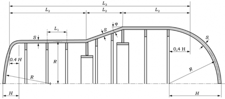
Fig. 1.1
(3) For the calculation of buckling in the elastic-plastic range the modulus of elasticity Á and the
poisson's
R is determined by applying formulae (65)-(68) and by means of the stress
ŖY formula
(1) in the centre of the section and the centre of the plate.
(4) The calculations allow for an out-of-roundness of the shell of maximum R = 0.005. If
larger tol-
erances are planned, or if the method of measurement described in 8.1 results in greater
out-of-roundness values, then the permissible pressure is to be checked in accordance with 8.2
2.2 Stresses in the cylindrical shell
The stress intensity (at the centre of the plate at midway position between ring stiffeners) is de- termined by applying formulae (1)-(14). In formulae (2a)-(2d) the centre of the bending component
is expressed by the plus sign on top
below for the inside. The stresses in pression after the plus/minus signs.
for the outside of the cylindrical shell and by the minus sign
the centre of the plate are determined by omitting of the ex-
Ë
ŖY G ĬJŖ Ż Ğ
Ë
ŖS G ŖŻ × ŖS
(1)
Ỳ × Ā (2)
ŖŊ G G J
In the centre of the section the following applies;
Ë ± Æ × Æ × Á (2a)
ŖŻ G ŖŊ F JË
ËŊ ËË ĖF
ŖS G ŖŊ FË G ÆËŊ × ÁË ±R × ÆËŊ × ÆËË × ÁĖF
In the area of stiffening the following applies;
(2b)
Ë ± Æ × Æ × Á (2c)
ŖŻ G ŖŊ F JË
ËŊ ËË Ė F
ŖS G ŖŊ FË G ÆËŊ ±R × ÆËŊ × ÆËË × ÁĖ F
(2d)
![]()
50 Guidance Relating to the Rules for the Classification of Underwater Vehicles 2015
Annex 1 Calculation and Pressure Hulls under External Pressure Annex 1
![]()
ct
Ė ck coshË Æ G cosË Æ ˇ
ÁË G JÆZ
₡
Ē Ŋ
![]()
cosh ÆĒ × sin Y Æ cos Æ × sin ÆŊ
(3a)
Æ
J
¢ JÆ
Ē Ğ Ŋ
È Ē ₡
₡
ck cosh ÆĒ × sin ÆŊ sinh ÆĒ × cos ÆŊ ˇ
ÁË Gct cosh ÆĒ × sinh Æ cos Æ × sin ÆŊ
![]()
JÆ Ē
Ğ J
Ē Ğ Ŋ
È (3b)
¢ JÆ È
ÆJ Ē ₡
ct J J
₡
ck cosh ÆĒ × sinh ÆĒ cos ÆŊ × sin ÆŊ ˇ
G Ğ
JĖ ÆÈ ÆĒ
ÁĖ G
![]()
Ē
Ŋ
ĬË GJŽË cosh ÆĒ × sinh Æ cos Æ × × sin ÆŊ
(3c)
¢ JÆ
È Ğ JÆ Ē ₡
ck cosh ÆĒ × sin ÆŊ sinh ÆĒ × cos ÆŊ ˇ
JĖ ct JÆ Ē Ğ J È ₡
(3d)
ÁĖ G ĬJF Ë G ŽËF
![]()
cosh ÆĒ × sinh ÆĒ cos ÆŊ × sin ÆŊ
¢ ÆJ È
Ğ J Ē ₡
A G AË ×
Ą Ë (4)
Ŋ
JĄ Ë
ÆÈ G Ø × ÄË (5)
Ë
ÆÈ G JË ĬJË G Æ
(6)
Ë
ÆĒ G JË ĬJË Ğ Æ
(7)
ÆĒ G ÆÈ × ÆÈ (8)
ÆŊ G ÆÈ × ÆĒ
(9)
FË G JË × JZ × Ä
A
R
F Ë (10)
ÆËŊ G JA Ẅ Ẅ
JZ × Ä Ë Ğ JÄ Ë Ğ FË G JÄ ËF ÁË
Ĭ
JŊĦŊË
ÆËË G ËGJRË
(11)
Ā € G J (12)
Ë × ZË × Á
Ą Ë × ĬJĖ × FË G RË F
Ā (13)
Ă G J €
![]()
Guidance Relating to the Rules for the Classification of Underwater Vehicles 2015 51
Annex 1 Calculation and Pressure Hulls under External Pressure Annex 1
![]()
Ø G ĬĖ
JĖ × FË G RËF JZË × Ą Ë
(14)
ŖS (15)
ÄŊ G JŖŻ
where,
A : modified area of stiffener ring (mmË)
AË :
ÄË :
Ẅ :
Ø :
ŖY :
ŖŊ :
ŖS :
ŖŻ :
R :
ĄŊ :
cross- sectional area of stiffener ring (mm Ë) spacing between two "light" stiffeners (mm) width of stiffener ring in contact with shell (mm) shape factor (1/mm)
stress intensity (NĤmm Ë)
stress (calculate value) (NĤmm Ë)
stress in circumferential direction (NĤmmË) stress in longitudinal direction (NĤmm Ë) Poisson's ratio (elastic)
radius of stiffener ring centroid including effective length
Ą : mean radius of wall
Ă : pressure ratio
Á : modulus of elasticity
Ā : external design pressure (NĤmm Ë)
Ā€ :
ÄŊ :
critical pressure (NĤmmË) stress ratio
ÆÈ~ÆËË : calculation factor for stress in cylindrical shell
2.3 Provision against excess stresses
The stress intensity for the three loading conditions is contained from formula (1). Sufficient safety against exceeding the permissible stress is provided if the conditions (16a,b,c) are met. In formulae (2a) to (2d) where load Ā = ĀC the binding component can be disregarded.
Ý≥ ŖY × Å ( where
Ā = ĀÀ ) (16a)
Ý≥ ŖY × Å ′ ( where
Ā = ĀĀ )
(16b)
Ý≥ ŖY
where,
( where Ā =
ĀC )
(16c)
k : yield strength
ĄẀĂËŊ
(NĤmm Ë)
S : safety factor applied to yield strength
ĄẀĂËŊ
at nominal pressure
S' :
safety factor applied to yield strength
ĄẀĂËŊ
at test diving pressure
PN :
nominal diving pressure (1st load condition) (NĤmm Ë)
PP :
test diving pressure (2nd load condition) (NĤmm Ë)
PZ :
collapse pressure (3rd load condition) (NĤmm Ë)
![]()
52 Guidance Relating to the Rules for the Classification of Underwater Vehicles 2015
Annex 1 Calculation and Pressure Hulls under External Pressure Annex 1
![]()
2.4 Asymmetric buckling
The buckling pressure ĀŸ is calculated with formulae (17)-(19) for the integer value n ≥ 2 corre- sponding to the lowest value of ĀŸ . The relevant stresses of the centre of the plate are determined in accordance with 2.2
Á × Z × ØŸË
ĀŸ G JĄ
(17)
Ø GctF JË ĞËF
ËË × Ą × FË G R F (18)
₡
ck G Ë ZË × FŸË G Ë Ğ RË FË ˇ
ŸË Ğ J Ë
![]()
ŸË R
Ë
FŸË
Ë Ë
G Ë ĞŊĦÈ RË F
¢ Ë ₡
Ř × Ą
RË G JÄ Ë
where,
(19)
ĀŸ :
ÄË :
RË : ØŸË : Z :
buckling pressure, asymmetric buckling (NĤmm Ë) spacing between two "light" stiffeners (mm) coefficient
coefficient
thickness of shell/sphere without abrasion and corrosion (mm)
2.5 Prevision against asymmetric buckling
The buckling pressure for the three loading conditions is obtained from formula (17). Sufficient safety against asymmetric buckling is provided if the conditions (20a,b,c) are met.
ĀŸ ≥ ĀÀ × ÅÝ (for the nominal diving pressure load condition)
ĀŸ ≥ ĀĀ × Å ′Ý G ĀÀ × ÅË × ÅÝ′ (for the test diving pressure load condition)
ĀŸ ≥ ĀC G ĀÀ × ÅË (for the collapse pressure load condition)
(20a)
(20b)
(20c)
where,
ÅÝ : safety factor against instability at nominal pressure
ÅÝ′ : safety factor against instability at test diving pressure
2.6 Symmetric buckling
The buckling pressure ĀŶ is calculated with formulae (21)-(33) and ((15) for the lowest integer val-
ue of Ŷ at which conditions (33) is met.
7. The relevant stresses if the centre of
elastic range ÁZ G ÁŹ G Á and R′ G R .
The values ÁZ and ÁŹ are determined in accordance with the plate are calculated in accordance with 2.2. In the
ck ØË ÄË Ë
Ë Ř Ŷ ˡ
ĀŶ G Ā
€€
ÆŊ ctFŘ ŶJF Ğ JĖFØ JF ₡
(21)
¢ Ë ÄË ₡
![]()
Guidance Relating to the Rules for the Classification of Underwater Vehicles 2015 53
Annex 1 Calculation and Pressure Hulls under External Pressure Annex 1
![]()
Z
Ë ZËÁ
Ā€€ G Ą Ë ĬJĖFË G Ž′Ë F
(22)
Æ G Ĭ
ÆJ Æ G R′Ë Æ Ë
Ë Ë Ė (23)
Ŋ JËGR′Ë
Ă Ë Ă
Ë
ÆË G Ë G JĂË
Ė (24)
Ă Ë Ă
Ė Ė
ÆË G Ë G JĂË
ĂË ĂĖ ĂĖ
(25)
(26)
ÆĖ G Ë G JR′Ă Ë
ĂË G Ë Ğ ĂĖ Ğ ĂËËG Ė FË G R′ ËF Ĝ
ĂË G FË G R′ FG FË G ËR′ F ÄŊ
(27)
(28)
ĂĖ G FË G ËŽ′ FG FË G Ž′ F ÄŊ (29)
ÁŹ
Ë G JÁÅ (30)
ĂĖ G JĖFË G R′Ë F Ä
Ë
ÄË G
Ë G ÄŊ Ğ
Ä
Ë (31)
Ŋ
ØË G ĬJ
ÆJ Ë
Ë
ÆĖ FĢ
Ë Ë (32)
ZË Ą Ë
ØË ÄË
ŶJ FŶ ĞËF
(33)
JŘ ≤ĬJË
where,
ĀŶ
Ā €€
: buckling pressure, symmetric (NĤmm Ë)
: critical pressure, elastic-plastic (NĤmmË)
ĂË ~ĂĖ : calculation factors for symmetric buckling
ÁZ : secant modulus
2.7 provisions against symmetric buckling
The buckling pressure Sufficient safety against
ĀŶ for the collapse pressure symmetric buckling is provided
condition is obtained from formula (21). if the conditions (34a,b,c) are met.
![]()
54 Guidance Relating to the Rules for the Classification of Underwater Vehicles 2015
Annex 1 Calculation and Pressure Hulls under External Pressure Annex 1
![]()
ĀŶ ≥ ĀÀ × ÅÝ (for the nominal diving pressure load condition)
ĀŶ ≥ ĀĀ × ÅÝ′ G ĀÀ × ÅË × ÅÝ′ (for the test diving pressure load condition)
ĀŶ ≥ ĀC G ĀÀ × ÅË (for the collapse pressure load condition)
(34a)
(34b)
(34c)
3. Ring Stiffeners
3.1 General
(1) It is the purpose of ring stiffeners to reduce the buckling length of cylindrical shells. A dis- tinction is made between "heavy" and "light" ring stiffeners. "Heavy" ring stiffeners are stiff- eners which are able to reduce the significant mathematical length of the pressure hull as this relates to the failure described in 3.2 (3) The dimensions of "heavy" stiffeners are not to be smaller than the "light" stiffeners. (see Fig. 1.2)
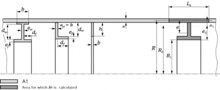
Fig. 1.2 Stiffeners
(2) For a terminal section, the length to be used is that between the end and the stiffener. (In the case of dished ends, the buckling length is to take account of the instruction in 2.1 and Fig. 1.1) For the loading conditions mentioned (1), stiffeners are to be designed for safety against excess stresses, buckling and tripping. Unreinforced cut-outs in the girth or web are to be con- sidered for calculation.
3.2 "Light" stiffeners
(1) Stresses in "light" stiffeners
The stresses are calculated using formulae (4), (14), (35)-(37) and the values of
ĀŸË
and Ÿ ac-
cording to 3.2 (3) If Ÿ = 2 determined also Ÿ =3 has to be calculated. In formulae (37), Ä G ÄË.
Where the distances ÄË to use of the arithmetic mean
R are replaced by Á ′ and are calculated in accordance
the two adjoining stiffeners are unequal, the calculation shall make
value of both distances. in the elastic-plastic range the value Á and
R′ respectively. The elasticity modulus Á ′ and the Poisson's ratio R′
with 7. in relation to stress ŖX .
ŖX G
R
ỲĄ Ë FËG JËF
₡
Jck A ˇ
ĄË ctZĞJËÀ
(35)
¢ Ẅ Ğ JØ ₡
ỲFŸË GËFÁ Ẁ Ã
Ë (36)
ŖXẄ G± J
Ÿ GĀF ĄŊË
J
À G cosh FØÄ FG cosFØÄ F (37a)
sinhFØÄFG sinFØÄF
![]()
Guidance Relating to the Rules for the Classification of Underwater Vehicles 2015 55
Annex 1 Calculation and Pressure Hulls under External Pressure Annex 1
![]()
À G Ë for Ø × Ä I ÈĦÈ (37b)
where,
ŖX : compression stress in girth (NĤmm Ë)
XẄ
Ŗ : bending stress in girth (NĤmm Ë)
(2) Provision against excess stresses
For the three loading conditions, formulae(35) and (36) give the stresses ŖX and ŖXẄ, the abso- lute values of which are related to the yield strength k in conditions (38a,b,c)
Ý≥ Ģ ŖX Ģ × Å Ğ Ģ ŖXẄ Ģ × ÅÝĢ Ý≥ Ģ ŖX Ģ × Å ′ Ğ Ģ ŖXẄ Ģ × ÅÝ′ Ý≥ Ģ ŖX ĢĞĢ ŖXẄ Ģ
(for (for (for
Ā G ĀÀ ) Ā G ĀĀ )
Ā G ĀC )
(38a)
(38b)
(38c)
(3) Buckling
The "light" stiffeners
are to be calculated using formulae
(39)-(45) for the integer Ÿ 2 which
produces the lowest value of ĀŸË . In formulae (41) Ä G ÄË, and, in the absence of "heavy" stiff-
eners, Ä G ÄĖ. In the mulae (39) and (42).
elastic-plastic range, Á ′ according to 7, is to be substituted for Á in for- The necessary stress calculation is performed in accordance with 3.2. (1)
ÁZ ØŸË (39)
ĀŊ G JĄ
Ė
RË
Ë Ë
ØŸË G FJŸË G Ë Ğ ŊĦÈR Ë FFŸË Ğ RËFË
(40)
Ř Ą
RË G JÄ
(41)
Ẁ
FŸË G ËF Á Â
(42)
ĀË G JĄ
Ŋ ĞÄË
ĀŸË G ĀŊ Ğ ĀË
(43)
Ë
A ẀË
Ė
ÄẀ Z
(44)
ÂẀ G JA
Ë Ğ ÂË Ğ JËË
Ẁ
Ë Ğ JÄ Z
ÄẀ G ĬJËĄ Z Ğ Ẅ (45a)
In addition with light stiffeners
ÄẀ ≤ ÄË (45b)
where,
ÄẀ :
ØŸË :
effective length of shell coefficient
![]()
56 Guidance Relating to the Rules for the Classification of Underwater Vehicles 2015
Annex 1 Calculation and Pressure Hulls under External Pressure Annex 1
![]()
RË : coefficient
ĀŸË : buckling pressure, asymmetric buckling "light" stiffener
(4) Provision against buckling
The calculation of the buckling pressure
ĀŸË
for the three loading conditions is performed in ac-
cordance with 3.2 (3) Sufficient safety against buckling is provided if the are met
ĀŸË ≥ ĀÀ × ÅÝ (for the nominal diving pressure load condition)
ĀŸË ≥ ĀỲ × ÅÝ′ G ĀÀ × ÅË × ÅÝ′ (for the test diving pressure load condition)
ĀŸË ≥ ĀC G ĀÀ × ÅË (for the collapse pressure load condition)
conditions (46a,b,c)
(46a)
(46b)
(46c)
3.3 "Heavy" stiffeners
(1) Stresses in "heavy" stiffeners
The stresses are calculated using formulae
(3). In formulae (37) and (41) Ä G ÄË . If
(35)-(37) and
the distances
the values ĀX and Ÿ according to 3.3
ÄË to the two adjoining stiffeners (or
ends) are unequal, the calculation shall make use of the arithmetic mean value of both
distances. In the elastic-plastic range the values Á and R are replaced by Á ′ and R′ . The elas- ticity modulus Á ′ and the Poisson's ratio R′ are calculated in accordance with 7. in the relation to the stress ŖX .
(2) Provision against excess stresses
For the three loading conditions, formulae (35) and (36) give the stresses ŖX and ŖXẄ, the abso- lute values of which are related to the yield strength Ý in conditions (38a,b,c)
(3) Buckling (general stability)
Using formulae (39)-(42) and (47)-(49), the overall stability of the design is to be calculated for
Ė Ė Ė
the integer Ÿ 2 at which the buckling pressure ĀX attains its lowest value. The calculation factor Æ in formulae (47) becomes Æ = - 4 for internal stiffeners and Æ = Ÿ Ë for external stiffeners. Where only one "heavy" stiffener is located midway between two bulkheads, the total
buckling pressure ĀX formulae (49) can be increased by a membrane stress element ĀŊ in ac- cordance with formulae (39)-(41) where Ä G ÄĖ. Where there are no "heavy" stiffeners, the buck-
ling ĀX is obtained from formula
ĀX G ĀŸË
(43)
Ā G FŸË G ËFÁ Â
Ë JĄ Ë FĄ ĞẀ
Ẁ (47)
Ŋ ËÆ ĖFÄË
ĀŸË G JĀ (48)
ĀŊ × ĀË Ŋ Ğ ĀË
ĀX G ĀË Ğ ĀŸË
(4) Provision against buckling
The calculation of the total buckling pressure
(49)
Pg for the three loading conditions is performed
in accordance with 3.3.3 Sufficient safety against buckling is provided if the conditions (50a,b,c)
are met.
ĀXË ≥ ĀÀ × ÅÝ (for the nominal diving pressure load condition)
ĀXË ≥ ĀỲ × Å ′Ý G ĀÀ × ÅË × ÅÝ′ (for the test diving pressure load condition)
ĀXË ≥ ĀC G ĀÀ × ÅË (for the collapse pressure load condition)
(50a)
(50b)
(50c)
![]()
Guidance Relating to the Rules for the Classification of Underwater Vehicles 2015 57
Annex 1 Calculation and Pressure Hulls under External Pressure Annex 1
![]()
3.4 Tripping of ring stiffeners.
(1) Tripping pressure and general conditions
The tripping pressure ĀÝ of flat bar stiffeners is to be calculated using formulae (4), (14), (37) and (51) and Fig. 1.3 or 1.4. The value of Ÿ is to be that used in 3.2 (3) or 3.3 (3) for cal-
culations in the elastic-plastic range, Á and R in the aforementioned formulae are to be replaced
by Á ′ and R′ in
accordance with 7. The necessary stress calculation is performed in accordance
with 3.2 (1) or
3.3 (1) The maximum allowable value of
Ë
Ý ĤÁ FYẄFË is 1.14 in each case.
Calculation of the tripping pressure using the
the tolerances stated in 9.
formulae referred to above necessitates maintaining
![]()
![]()
ËÀ
ÝË ĄË ĻZ Ğ J A Ł (51)
ĀÝ G JRĄË FËG JË Ŀ
Ẅ Ğ J M
(2) Resistance of tripping
For flat bar stiffeners, the tripping pressure ĀÝ for the three loading conditions is obtained from formula (51). Sufficient resistance to tripping is provided if the conditions (52a,b,c) are met
ĀÝË ≥ ĀÀ × ÅÝ (for the nominal diving pressure load condition)
ĀÝË ≥ ĀĀ × ÅÝ′ G ĀÀ × ÅË × ÅÝ′ (for the test diving pressure load condition)
ĀÝË ≥ ĀC G ĀÀ × ÅË (for the collapse pressure load condition)
(52a)
(52b)
(52c)
Proof of the sufficient resistance to tripping of Ä-, Å - and Â-section stiffeners by applying formulae (53). Proof can be dispensed with if minimum seven eight conditions are met:
can be provided of the following
Ą ẀB ẀB Á ÂË′
(53)
ẀB ≥Z Ħ ẀX ≥ ẀB Ħ ẀX ≤ ËZ Ħ ẀB ≤ ËŊẀB Ħ ẀB ≤ JË Ħ ẀX ≤ ËŊẀX Ħ JË
≥ ẀX ≥ JĖ , Ý ÅÝ ≤ JA Ë Ą Ẁ

Fig 1.3
![]()
58 Guidance Relating to the Rules for the Classification of Underwater Vehicles 2015
Annex 1 Calculation and Pressure Hulls under External Pressure Annex 1
![]()

Fig 1.4
4. Stiffened and Unstiffened Conical Shells
The procedure to be applied to conical shells is similar are replaced in sections by cylinders having the mean
to that for cylindrical shells. Conical shells diameter and by multiplying the actual ex-
ternal pressure by ËĤcosS. It is assumed that the ends of the cone are fitted
stiffeners. If not, a stress analysis has to be performed in accordance with 6.1.
with "heavy" ring
Ring stiffeners are
to be calculated in the manner described in 3. The instructions given in 2.1 are applicable to out-of-roundness values in conical shells.
5. Dished Ends and Spheres
5.1 General
Dished ends and spheres
are to be examined for excess stresses and buckling under the loading
conditions stated in 1. In the case of dished ends, the stresses in the crown radius and in knuckle
radius are to investigated.
Spheres are to be treated in the same way as the crown radius of dished
ends. The calculation allow for out-of-roundness of the shell up to a maximum of R G ŊĦŊĖ × ZĤĄ. If larger tolerances are planned, or if the method of measurement described in 8.3 results in great- er out-of-roundness values, then the permissible pressure is to be checked in accordance with 8.4.
5.2 Stress
For the dished sections the stress is obtained by applying formulae (54). For the knuckle radius the stress is obtained with formulae (55), the radius Ą being the radius of the adjoining cylindrical jacket. The coefficient Ø are to be taken from Fig. 1.5. For hemispherical ends in the range of ŊĦÈĬJZ∙ Ą beside the transition to the cylinder a coefficient Ø - 1.1 is valid.
Ą Ỳ (54)
Ŗ GG JË Z
ỲĄËĦËØ Ŗ GG JË Z
(55)
![]()
Guidance Relating to the Rules for the Classification of Underwater Vehicles 2015 59
Annex 1 Calculation and Pressure Hulls under External Pressure Annex 1
![]()
Fig. 1.5
5.3 Provision against excess stresses
The stress for the three loading conditions is obtained by applying formulae (54) and (55). Sufficient safety against excess stresses is provided if the conditions (56a,b,c) are met, allowing for the absolute values of Ŗ
Ý≥ Ģ Ŗ Ģ × Å
(for Ā G ĀÀ )
(56a)
Ý≥ Ģ Ŗ Ģ × Å ′ (for
Ā G ĀĀ )
(56b)
Ý≥ Ģ Ŗ Ģ
(for Ā G ĀC )
(56c)
![]()
60 Guidance Relating to the Rules for the Classification of Underwater Vehicles 2015
Annex 1 Calculation and Pressure Hulls under External Pressure Annex 1
![]()
5.4 Buckling
The buckling pressure ĀŸ in the dished section for the nominal diving pressure and test diving pressure load conditions is determined by applying formula (57)
Ë
Z F
ĀŸ GŊĦĖÈÈ Á F JĄ
(57)
The buckling pressure ĀŸ in the dished section for the collapse pressure load condition is calculated with formula (58). The elasticity moduli ÁZ and ÁŹ are calculated in accordance with 7. allowing for the stress determined with formula (54)
Z
Ë
ĀŸ G ŊĦĒĖ ĬJÁZ ÁŹ FJĄ F
(58)
5.5 Provision against buckling
The buckling pressure for the nominal diving pressure and test diving pressure load conditions is calculated with formula (57). Sufficient safety is provided if the conditions (59a,b) are met. The buckling pressure for the collapse pressure load condition is calculated with formula (58). Sufficient safety is provided id conditions (59c) is met.
ĀŸ ≥ ĀÀ × ÅÝ (for the nominal diving pressure load condition)
ĀŸ ≥ ĀĀ × ÅÝ′ G ĀÀ × ÅË × ÅÝ′ (for the test diving pressure load condition)
ĀŸ ≥ ĀC G ĀÀ × ÅË (for the collapse pressure load condition)
(59a)
(59b)
(59c)
6. Opening and Discontinuities
6.1 Discontinuities
Discontinuities such as
- Connections between cylinders and conical segments
- Reinforcing rings (rings other than the ring stiffeners dealt with in 3)
- Flanges for fixing spherical shell windows
must be subjected to a stress and elongation analysis similar to that specified in「ASME Boiler Pressure Vessel Code, Division 2, Section, 1989」for the nominal diving pressure and test
diving pressure load conditions. The comparison stress is determined by applying formula (1).
Sufficient safety is provided if the conditions (16a,b) are met. In case of an interruption of stiff- eners an adequate reinforcing has to be provided.
6.2 Cylinder/cylinder penetrations
Cutouts in cylinders are to be made in accordance with the relevant requirements of Pt 5, Ch 5,
Sec 3 of Rules for the Classification of Steel Ships and using as internal pressure a pressure ĀẄ calculated by applying formulae (60)-(61) - minimum with the relevant pressure load case. Reinforcements are to be provided as integral reinforcements.
design of the
Ë
Ā ËĀÀ × Ą × Å
A
Ẅ G JÝ× Á ×Z (60a)
![]()
Guidance Relating to the Rules for the Classification of Underwater Vehicles 2015 61
Annex 1 Calculation and Pressure Hulls under External Pressure Annex 1
![]()
J Ā Ą Å ′
Ë
Ā G Ë Ā × × (60b)
Ẅ Ý× Á × Z
A
Ë
Ā ËĀC Ą (60c)
A
Ẅ G JÝ Á Z
Ą
(for
≥
ÄË ŊĦĖ) (61a)
Ë
ŊĦĖĄ FZA JĄ
ÄË
Á G Ë F for JĄ Ĥ ŊĦĖF
(61b)
6.3 Sphere/ cylinder penetrations
Cutouts in spheres are to be made in accordance with the relevant requirements of Pt 5, Ch 5, Sec 3 of Rules for the Classification of Steel Ships and using as internal pressure an in-
creased design pressure
Pc calculated by applying formulas (62)
ĀẄ G ËĦË × ĀÀ ĀẄ G ËĦË × ĀĀ
ĀẄ G ËĦË × ĀC
(62a)
(62b)
(62c)
7. Elasticity Moduli
The elasticity modulus for calculations in the elastic region up to the limit of proportionality is to
5be0℃ta,kean
from the standard specifications for the materials concerned. For design temperature up to value of Á = 206,000 ÀĤŶŶË can generally be accepted for ferritic steels. For steel, a
Poisson's ratio of v=0.3 is to be used. In the elastic-plastic range, the elasticity moduli ÁZ and ÁŹ for steel between the limit of proportionality ŖẀ and the yield point k according to the stress-strain curve Ŗ G XFffhĦÝĦ ÁF are to be determined by applying formulae (63)-(66)
ŖẀ
a G J
Á×Õ a ˇ (63)
F
Ŗ G Ý ckcta ĞFË G aF ŹX Y F JG JGFa ₡ ₡
Õ G JÁ a Ğ FËG aF ŴZŹXY F JG JF
Ý ck
¢
Ŗ a ˇ (64a)
FË G a F Ý FË G a F ₡
Õmin G
Ý (64b)
a JÁ
Ý
Õmin G ÀYŸ [maximum remaining elongation+ JÁ Ħ Õ G X FŖ → ÝF Ĝ
(64c)
ÁZ G J
Ý ck
a ĞFË G a F ŹXY
Õ ¢
Á
F JFË G a F Ý
a F ˇ
G JË G a ₡₡
(65)
×Õ
ck Ë FÁ J JG
aF₡
ˇ (66)
ÁŹ G Á ¢Ë G ŹX Y FË G a F Ý
FË G a F ₡
![]()
62 Guidance Relating to the Rules for the Classification of Underwater Vehicles 2015
Annex 1 Calculation and Pressure Hulls under External Pressure Annex 1
![]()
For calculations in the elastic-plastic range which were originally developed for the elastic range, the term Á is to be replaced by the term Á ′ from formula (67)
Á ′ G ĬJÁZ × ÁŹ
(67)
With the Society's agreement, the stress -strain curve actually measured may be used to determine the elasticity moduli in the elastic-plastic range. In the elastic-plastic range, the Poisson's ratio is to be calculated using formula (68)
Ë Ë ÁZ
(68)
R′ G JË G F JË G RF JÁ
8. Out-of-Roundness of cylinders and Spheres
Cylindrical shells and dished ends subjected to external pressure are to be checked for out-of- roundness. If the tolerances are exceeded, the permissible external pressure is to reduced to the value Ā ′ .
8.1 Measuring the out-of-roundness of cylindrical shells
The number of planes used for measuring the out-of-roundness of cylindrical pressure vessels is to be agreed with the Society. For each plane, the number of measuring prints (Â) shall be at least 24, and these shall be evenly distributed round the circumference. The height of arc Ż FÝF is meas- ured with a bridge extending over a string length Ż G Ė∙Ř ∙ FĄ Ğ ZĤŽ FĤÂ (cf. Fig. 1.6). From the values Ż FÝF and the influence coefficients Æ, the out-of-roundness values can be calculated by ap-
plying formula (69). Table 1 gives the influence coefficients
Æ where  = 24. If the out-of-round-
ness à FÝ F at any measuring point exceeds a value of à G ŊĦŊŊÈ × Ą, then a reduced permissible
pressure Ā ′
is to be determined in accordance with 8.3
Table 1 Influence factor
ÆY where
 = 24
Y G Ý | ÆY G Ý | Y G Ý | ÆY GÝ |
0 | 1.76100 | 12 | 0.60124 |
1 | 0.85587 | 13 | 0.54051 |
2 | 0.12834 | 14 | 0.36793 |
3 | -0.38800 | 15 | 0.11136 |
4 | -0.68359 | 16 | -0.18614 |
5 | -0.77160 | 17 | -0.47097 |
6 | -0.68487 | 18 | -0.68487 |
7 | -0.47097 | 19 | -0.77160 |
8 | -0.18614 | 20 | -0.68359 |
9 | 0.11136 | 21 | -0.38800 |
10 | 0.36793 | 22 | 0.12834 |
11 | 0.54051 | 23 | 0.85587 |
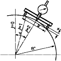
Fig. 1.6
Ī
Ý G Ë
ÃÝ G ŻY ÆĢ Y G Ý Ģ (69)
Y G Ŋ
Example of the out-of-roundness à at measuring point Ý = 2 where Ý = 24
ÃË G ŻŊ × ÆË × ŻË × ÆË Ğ ŻË × ÆŊ × ŻĖ × ÆË Ğ …… Ğ ŻËË × ÆËŊ × ŻËË × ÆËŊ Ğ ŻËĖ × ÆËË
![]()
Guidance Relating to the Rules for the Classification of Underwater Vehicles 2015 63
Annex 1 Calculation and Pressure Hulls under External Pressure Annex 1
![]()
8.2 Calculation of permissible pressure for cylindrical shell with an out-of- roundness u>0.005
The bending stress is determined for all measuring points by the choice of a reduced permissible pressure Ā ′ and by applying formula (70). The total stress is found with formula (74) and the re-
duced permissible pressure Ā ′
formula (17) being substituted measuring the circumference.
with formula (75) by a process of iteration, the Ÿ-related value for for the pressure ĀŸ . The mean radius Ą ′ is to be determined by
Á ×Z
ÂĤË
ŘĄ Ë Ā ′
ŖẄ G JËĄ Ë FË GĪRËĜF FŸ GËF ĞR F JF Ģ
ĜĀ GJĀĢ′ Ÿ Ÿ
Ë
Ÿ G Ë
× ĜŴ sin FŸǾFĞ Ẅ cosFŸǾFĢ
ÄË Ÿ
(70)
ËŘ
Ǿ G JÂ Y
(71)
Ë
 G Ë
Ŵ Ī Ą ′ Ã
sin FŸǾF
(72)
Ÿ G JÂ Y G Ŋ F
Ğ Y FĞ
Ë
 G Ë
Ẅ Ī
FŸ G Â F
Ą ′ Ğ Ã FĞ cos FŸǾF J
(73a)
Ÿ G JÂ Y G Ŋ F Y Ë
Ë Â G Ë Â
Ẅ G Ī FĄ ′ Ğ Ã FĞ cos FŸǾF FŸ G F
(73b)
Ÿ JÂ Y G Ŋ Y JË
Ā ′Ą
Ý≥ J Ğ ŖẄ
(74)
F
Ā ′
Ā ′ ≥ JÅ Ğ Ỳ G JÅ
ŊJĦŊŊÈĄ
(75)
Ā ′ F Ã max
8.3 Measuring the out-of-roundness of spheres
The hight of arc Ż′ is measured with a bridge gauge (cf. Fig. 1.7), the string length Ż being cal-
culated with formulae (76) and (79).
the out-of-roundness is greater than termined in accordance with 8.4
ZF
Ż G Ë FĄ Ğ JË sin Ǿ
The out-of- roundness U is determined with formula (78). If
Ź G ŊĦŊĖ∙ ZĤĄ, a reduced permissible pressure Ā ′ is to de-
(76)
Z F
Ż G FĄ Ğ JË FË G cos ǾF
à G Ż G Ż′ G Ź Ą
(77)
(78)
ËĦË JZ
(79)
ĄĞ J F
Ë
Ǿ G J Ë G RËF ĬF JZ
where,
![]()
64 Guidance Relating to the Rules for the Classification of Underwater Vehicles 2015
Annex 1 Calculation and Pressure Hulls under External Pressure Annex 1
![]()
Ǿ : angle used in measuring out-of-roundness of spheres (radian)
The distribution of the measuring points is shown in Fig. 1.8. Two measurements are to be made at each point: one in the plane of the central axis, the other at right angles to it.
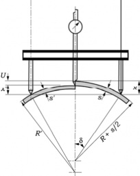
Fig. 1.7
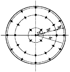
Fig. 1.8
8.4 Calculation of permissible pressure for spheres with an out-of- roundness u>0.04•s/R
The reduced permissible pressure Ā ′ calculated with formula (80) allowing for the actual radius of curvature Ą ′ and the minimum wall thickness occuring in the measuring range Ż (taking account
of any reductions for wear and
(81)
corrosion). The radius of curvature Ą ′ is determined with formula
Ā ′ G Ā
Ļ Z ŁË
![]() Ą Ğ JË
Ą Ğ JË ![]() Ŀ JĄ ′ M
Ŀ JĄ ′ M
Ë
FZJZ′ ≤ Ā
(80)
Ż′ Ğ JŻË
(81)
Ą ′ G JË
Ē Ż′
9. Tolerance of Ring Stiffeners
A check is to be carried out on ring stiffeners been maintained.
(1) Girth width (on T-section flanges, the whole
(2) Girth and web thickness ; -0 ~ +1
to determine whether the following tolerances have width); -0 ~ +5 mm
The tolerance Ź depends on the conditions of supply for the material. (If the material supply specification allows negative tolerances, these are to be allowed for in the calculations)
(3) Hight of ring (in the case of built-up profiles the height of the entire ring); -2 % ~ +5 % of the total height
(4) Uneveness of web and girth (measured over height of web and girth respectively): 0 ~ 1 % of web and girth height respectively
(5) Symmetry of flange in relation to web (applicable to I- and T-section stiffeners; the difference from the edge of the girth to the web on both sides of the web); 0 ~ 4 mm difference.
(6) ÄË distances (distances between "light" stiffeners and separating "light" from "heavy" stiffeners);
- 5.0 ~ +5.0 mm
(7) ÄË distances (distances between "heavy" stiffeners or ends separating "heavy" stiffeners from ends); -15.0 ~ +5.0 mm
![]()
Guidance Relating to the Rules for the Classification of Underwater Vehicles 2015 65
Annex 1 Calculation and Pressure Hulls under External Pressure Annex 1
![]()
(8) Angularity of web in relation to wall or main axis : -2̊ ~ +2̊
(9) Angularity of flange in relation to web : -3̊ ~ +3̊
All dimensional deviations are to be measure eight times on each stiffener at points equally spaces
round the circumstance. If the aforementioned tolerances are exceeded, corrective machining and/or
manual work is to be carried out on the stiffener and/or the calculation is to be repeated with cor- rected dimensions. ![]()
![]()
66 Guidance Relating to the Rules for the Classification of Underwater Vehicles 2015
Annex 2 Design and Construction for Submersible with GRP Annex 2
![]()