Iranian Classification Society Rules

< Previous | Contents | Next >
Section 5 Visual Aids
501. Wind direction indicator
1. A wind direction indicator should be located on the unit which, in so far as is practicable, in- dicates the wind conditions over the TLOF in such a way as to be free from the effects of airflow disturbances caused by nearby objects or rotor downwash. It should be visible from a helicopter in flight or in a hover over the helideck. Where the TLOF may be subject to a disturbed air flow then additional wind direction indicators located close to the area should be provided to indicate the surface wind on those areas. Placement of the wind direction indicators should not compromise obstacle-protected surfaces.
2. Units on which night helicopter operations take place should have provisions to illuminate the wind direction indicators.
3. A wind direction indicator should be a truncated cone made of lightweight fabric and should have the following minimum dimensions:
- Length : 1.2 m
- Diameter (larger end) : 0.3 m
- Diameter (smaller end) : 0.15 m
4. The colour of the wind direction indicator should be so selected as to make it clearly visible and understandable from a height of at least 200 m above the heliport, having regard to background. Where practicable, a single colour, preferably white or orange, should be used. Where a combina-
tion of two colours is required to give adequate conspicuity should preferably be orange and white, or red and white, and bands the first and last band being the darker colour.
against changing backgrounds, they should be arranged in five alternate
![]()
502. Heliport identification marking
A heliport identification marking should be located at the centre of the touchdown/positioning mark- ing described in 506. 1 to 3. It should consist of a white "H" that is 4 m high, 3 m wide, with a stroke width of 0.75 m.
503. D-value marking
1. The actual D-value of the helideck should be painted on the helideck inboard of the chevron pro- vided in accordance with 507. in alphanumeric symbols of 0.1 m in height.
2. The helideck D-value should also be marked around the perimeter of the helideck in the manner shown in Fig 12.4 in a colour contrasting (preferably white: avoid black or grey for night use) with the helideck surface. The D-value should be to the nearest whole number with 0.5 rounded down, e.g., 18.5 marked as 18. Markings for some helicopters may require special consideration.(Helidecks designed specifically for AS332L2 and EC 225 helicopters, each having a D-value of 19.5 m, should be rounded up to 20 in order to differentiate between helidecks de- signed specifically for L1 models.)
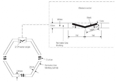
Figure 12.4 Obstacle-free sector marking
504. Maximum allowable mass marking
1. A maximum allowable mass marking should be located within the TLOF and so arranged as to be readable from the preferred final approach direction, i.e. towards the obstacle-free sector origin.
2. The maximum allowable mass marking should consist of a two- or three-digit number followed by a letter "t" to indicate the allowable helicopter mass in tonnes (1,000 kg). The marking should be expressed to one decimal place, rounded to the nearest 100 kg. Where States require that a max- imum allowable weight is indicated in pounds, the marking should consist of a two- or three-digit number to indicate the allowable helicopter weight in thousands of pounds, rounded to the nearest 1,000 pounds.
3. The height of the figures should be 0.9 m with a line width of approximately 0.12 m and be in a colour (preferably white) which contrasts with the helideck surface. Where possible the mass mark- ing should be well separated from the installation identification marking in order to avoid possible confusion on recognition.
![]()
505. TLOF perimeter marking
The TLOF perimeter marking should be located along the perimeter of the TLOF and should con- sist of a continuous white line with a width of at least 0.3 m. TLOF perimeter markings are typi- cally for a 1 D or 0.83 D value (see Fig 12.2 and Fig 12.3).
506. Touchdown/positioning marking
1. A touchdown/positioning marking should be located so that when the pilot’s seat is over the mark- ing the whole of the undercarriage will be within the TLOF and all parts of the helicopter will be clear of any obstacle by a safe margin.
2. The centre of the touchdown/positioning marking should be concentric to the centre of the TLOF.(The marking may be offset away from the origin of the obstacle-free sector by no more than 0.1 D where an aeronautical study indicates such offsetting to be beneficial, provided that the offset marking does not adversely affect the safety of operations.)
3. A touchdown/positioning marking should be a yellow circle and have a line width of 1 m. The in- ner diameter of the circle should be half the D-value of the largest helicopter for which the TLOF is designed.
507. Helideck obstacle-free sector marking
1. Except as provided in Par 2, a helideck obstacle-free sector marking should be located on the TLOF perimeter marking and indicated by the use of a black chevron, each leg being 0.8 m long and 0.1 m wide forming the angle in the manner shown in Fig 12.4 (replaced by Res.A.1023(26)/Corr.1). The obstacle-free sector marking should indicate the origin of the ob- stacle- free sector, the directions of the limits of the sector and the verified D-value of the helideck. Should there not be room to place the chevron where indicated, the chevron marking, but not the point of origin, may be displaced towards the circle centre.
2. For a helideck less than 1 D (i.e. a helideck meeting 301. 3), a helideck obstacle free sector marking should be located at a distance from the centre of the TLOF equal to the radius of the largest circle which can be drawn in the TLOF or 0.5 D whichever is greater.
3. The height of the chevron should equal the width of the TLOF perimeter marking, but should be not less than 0.3 m. The chevron should be black in colour and may be painted on top of the TLOF perimeter marking in 505.
508. Unit identification markings
1. The name of the unit should be clearly displayed on unit identification panels located in such posi- tions that the unit can be readily identified from the air and sea from all normal angles and direc- tions of approach. The height of the figures should be at least 0.9 m with a line width of approx- imately 0.12 m. The unit identification panels should be highly visible in all light conditions and located high up on the unit (e.g., on the derrick). Suitable illumination should be provided for use at night and in conditions of poor visibility.
2. The unit’s name should be provided on the helideck and be positioned on the obstacle side of the touchdown/positioning marking with characters not less than 1.2 m in height and in a colour con- trasting with the background.
509. Perimeter lights
1. The perimeter of the TLOF should be delineated by green lights visible omnidirectionally from on or above the landing area. These lights should be above the level of the deck but should not ex- ceed 0.25 m in height for helidecks sized in accordance with 301. 2 and 0.05 m in height for hel- idecks sized in accordance with 301. 3. The lights should be equally spaced at intervals of not more than 3 m around the perimeter of the TLOF, coincident with the white line delineating the perimeter in 505. 1. In the case of square or rectangular decks there should be a minimum of four lights along each side including a light at each corner of the TLOF. Flush fitting lights may be
![]()
used at the inboard (150° limited obstacle sector origin) edge of the TLOF where there is a need to move a helicopter or large equipment off the TLOF.
2. Perimeter lights should meet the chromaticity characteristics given in Table 12.1, and the vertical beam spread and intensity characteristics given in Table 12.2. (If higher intensity lighting is pro-
vided to assist in conditions of poor visibility during daylight, it should
duce the intensity to not more than 60 cd for night use.)
incorporate a control to re-
Table 12.1 Perimeter lighting chromaticity
Yellow boundary | x = 0.36 - 0.08y |
White boundary | x = 0.65y |
Blue boundary | y = 0.9 - 0.171x |
Table 12.2 Green perimeter lighting intensity
Elevation | Intensity(cd) |
0 ̊ - 90 ̊ | 60 max |
˃ 20 ̊ - 90 ̊ | 3 min |
˃ 10 ̊ - 20 ̊ | 15 min |
0 ̊ - 10 ̊ | 30 min |
Azimuth +180 ̊ - 180 | |
510. Helideck floodlights
Helideck floodlights should be located so as to avoid glare to pilots, and provision should be made for periodically checking their alignment. The arrangements and aiming of floodlights should be such that helideck markings are illuminated and that shadows are kept to a minimum. Floodlights should conform to the same height limitations specified in 505. 1 for perimeter lights.
511. Obstacle marking and lighting
1. Fixed obstacles and permanent equipment, such as crane booms or the legs of self-elevating units, which may present a hazard to helicopters, should be readily visible from the air during daylight. If a paint scheme is necessary to enhance identification by day, alternate black and white, black and yellow, or red and white bands are recommended, not less than 0.5 m nor more than 6 m wide.
2. Omnidirectional red lights of at least 10 cd intensity should be fitted at suitable locations to pro- vide the helicopter pilot with visual information on objects which may present a hazard to heli- copters and on the proximity and height of objects which are higher than the landing area and which are close to it or to the limited obstacle sector boundary. Such lighting should comply with the following:
(1) Objects which are more than 15 m higher than the landing area should be fitted with inter- mediate red lights of the same intensity spaced at 10 m intervals down to the level of the landing area (except where such lights would be obscured by other objects).
(2) Structures such as flare booms and towers may be illuminated by floodlights as an alternative to fitting the intermediate red lights, provided that such lights should be arranged such that they will illuminate the whole of the structure and not interfere with the helicopter pilot’s night vision.
(3) On self-elevating units the leg(s) nearest the helideck may be illuminated by floodlights as an alternative to fitting the intermediate red lights, provided that such lights should be arranged such that they will not interfere with the helicopter pilot’s night vision.
(4) Alternative equivalent technologies to highlight dominant obstacles in the vicinity of the
heli-
![]()
3. An omnidirectional red light of intensity 25 to 200 cd should be fitted to the highest point of the unit and, in the case of self-elevating units, as near as practicable to the highest point of each leg. Where this is not practicable (e.g., flare towers) the light should be fitted as near to the extremity as possible.
512. Status lights
1. Status lights should be installed to provide warning that a condition exists on the unit which may be hazardous for the helicopter or its occupants. The status lights should be a flashing red light (or lights), visible to the pilot from any direction of approach and on any landing heading. The system should be automatically initiated when the toxic gas alarm under Ch 6, 302. is initiated as well as being capable of manual activation at the helideck. It should be visible at a range in excess of the distance at which the helicopter may be endangered or may be commencing a visual approach. The status light system should:
(1) be installed either on or adjacent to the helideck. Additional lights may be installed in other lo- cations on the unit where this is necessary to meet the requirement that the signal be visible from all approach directions, i.e. 360° in azimuth;
(2) have an effective intensity of at least 700 cd between 2° and 10° above the horizontal and at least 176 cd at all other angles of elevation;
(3)
(4)
(5)
(6)
be provided with a facility to enable the output of the lights (if and when activated) to be
dimmed to an intensity not exceeding 60 cd while the helicopter is landed on the helideck;
be visible from all possible approach directions and while the helicopter is landed on the heli- deck, regardless of heading with a vertical beam spread as describe above;
use lights that are ‘red’ as defined by ICAO (Reference is made to the ICAO Convention, Annex 14, Volume 1, Appendix 1, Colours for aeronautical ground lights);
flash at a rate of 120 flashes per minute and, if two or more lights are needed to meet this requirement, they should be synchronised to ensure an equal time gap (to within 10%) between
flashes. Provision should be made to reduce the flash rate to 60 flashes per minute should a
helicopter be on the helideck. The maximum duty cycle should be no greater than 50%;
(7) have facilities at the helideck to manually override the automatic activation of the system;
(8)
(9)
reach full intensity in not more than three seconds at all times; (replaced by Res.A.1023(26)/Corr.1)
be designed so that no single failure will prevent the system operating effectively. In the event
that more than one light unit is used to meet the flash rate requirement, a reduced flash fre- quency of at least 60 flashes per minute is acceptable in the failed condition for a limited peri- od; and
(10) where supplementary ‘repeater’ lights are employed for the purposes of achieving the ‘on
deck’ 360° coverage in azimuth, these should have a minimum intensity of 16 cd and a max-
imum intensity of 60 cd for all angles of azimuth and elevation.